This thread has been locked.

If you have a related question, please click the "Ask a related question" button in the top right corner. The newly created question will be automatically linked to this question.

TLC5951: Brightness control issue

Part Number: TLC5951

Hello all,

A professor ask,

I have a project with 217 pieces TLC5951. I can control the brightness and the color. However, there is still one problem that I can't figure out:
If I send the full value for the color (e.g. 4095 for red) it works fine. but if I send less value e.g. 2048 instead of 4095, the LED flashes. As lower the value, stronger is the flash (because the flash-pause increases).

Why is this and how can I fix it?

To my construction: I send the RGB-data (GS in the datasheet) via GSSIN and the brightness and settings (DC in the datasheet) via DCSIN.

Anyone can help me with this?

Thank you in advance

  • Hi, Kaustubh,

    Can you help to share more information on this problem:
    1. What does "less value" mean? Is it less GSCK pulses or GSDATA?
    2. What's the frequency of GSCK?
    3. How does the XBLNK signal set?

    We can give more specific suggestion after we know more about this system.

    Regards,
    Kenneth
  • Hello Kenneth,

    Please check the following details,

    1.) It is GSDATA . The range of value is 12 Bit (0...4095). If I send the full value (4095) for a color it works fine. If I send value less than 4095, the LED flashes. As lower the value, longer is the flash-pause.
    2.) The clock-frequency (GS-Clock) is 6.5 MHz.
    3.) The XBLNK signal is stopped until all data are sent.

    And it works fine, if I send the full value for GSDATA.
    I hope this information will help you.

    Thank you.
  • Hi, Kaustubh,

    Can you share me how does the 217 pieces TLC5951 connected?
    Does the problem occurs when you test one piece TLC5951 or when you test 217 cascaded pieces?
    I want to check these questions to decide whether GSDATA has enough time to be sent.

    Regards,
    Kenneth
  • The 217 pieces are connected seriell. I send 7812 Bytes per color-change (288 Bit * 217 pieces / 8 = 7812 Byte). It works fine, if I send the full value for the color or 0.

    I never have tested it with only one piece - only with the full chain of 217 pieces.

    There are two Bits for settings. This bits are sent together with the DC (Brightness)-values. This Bits are explained on page 32 of the datasheet. I haven't understood this Bits really. Can it be that the problem comes from this Bits?

    Best regards

    Franz Peter Zantis

  • Hi, Franz,

    If you are meaning the register bit 198 and 197, they're used for Selectable Grayscale (GS) Control.

    For your application, you need to set them 0X to select 12 bits mode.

    If you still have this issue, then I think it's probably because you're cascading too many devices which needs much time to transfer data.

    I suggest you increase your GS-CLK frequency or cascade less devices to check the result.

    Thanks.

    Regards,
    Kenneth
  • Dear Kenneth,
    thank you for your message. However: No, I mean the Bits 195 and 196 and I do not really understand this Bits. This Bits are descriped on page 32 of the datasheet.
    The Bits 198 and 197 are of course already set to zero.
    No, it cannot have to do with the cascading. The complete system is divided in seven groups. Each group with 31 TLC5951-devices is cared by an own controller. A "Main-Controller" cares the 7 group-controllers.
    And: it works fine, if I send RGB-Data (GS-Data) 0 or 4095. The flash happens with all values between them (1 to 4094). With 1, the flashpause is maximum. With 4094, the flash pause is minimum.
    Maybe the developer of the TLC5951 have an idea what I do wrong.

    Regads
    Franz Peter
  • Hi, Franz,

    Can you help to get the scope shot of GSCK, XBLNK, GSLAT and OUT of one TLC5951 under flashpause condition with Bits195/196 are "0"?

    We can judge whether the timing is correct or not.

    Thanks.

    Regards,
    Kenneth
  • Hello Kenneth,


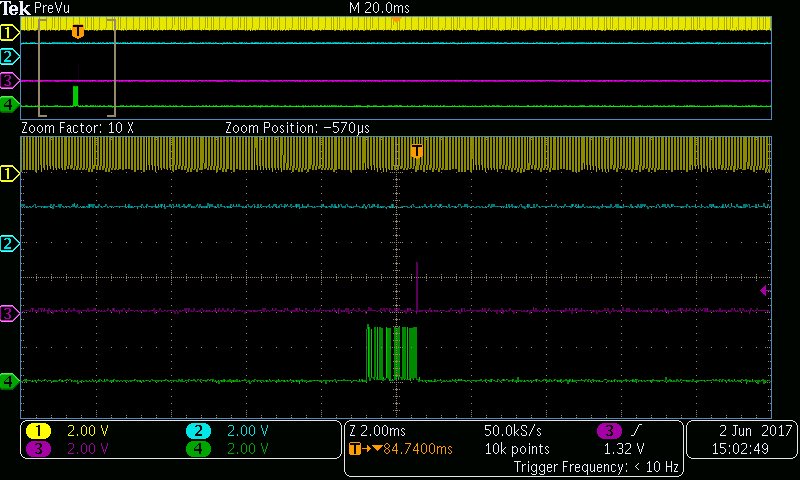
    attached you can find a diagram. From top to down there is: GSCK, XBLNK, GSLAT and OUT.

    By this I found out, that XBLNK is permanent on high-level. This is not so planned. Can this cause the problem with the flashing?

    Best regards

    Franz Peter

  • Hi, Franz,

    The XBLNK signal may be the cause. As you know, when you disable Auto Repeat and Display Timing Reset, GS counter starts to count GSCKR/G/B after
    XBLNK goes high. So if XBLNK is always high, GSCKR/G/B won't be able to count correctly every cycle, and that's why if GS DATA is not all 1, then it goes wrong.

    You may need to check why XBLNK is not the signal you want and another way to find out whether our assumption is correct is: Enable Auto Repeat, connect XBLNK to VCC and recheck the result.

    Please keep us noted if you have any progress.


    Regards,

    Kenneth


  • I found a hardware problem (wire not connected) but now the XBLNK-signal comes to all driver. However: nothing has changed. I tried to get yellow (with a mix from green and red) and it seems, that the colors changing. It flashes alternating in red and green. The red and green LEDs do not light at the same time. The TLC5951 let them flash alternating - why? I have tried to make a movie from it - however, it has not worked. I further will try.
  • With "Enable Auto Repeat" you mean: setting the Bit 195 (Datasheet page 32) - right?

  • The movie is to big (12 MByte) to attach. However, believe me, it is flashing if I send a value which is different from 0 or 4095. Do you have an idea what I can do? Or is it a bug of the TLC5951?

  • Franz,

    How do you apply GSCKR / GSCKG / GSCKB? Do they use the same signal?

    We didn't hear about this kind of problem before.


    Regards,

    Kenneth

  • Hello Kenneth,

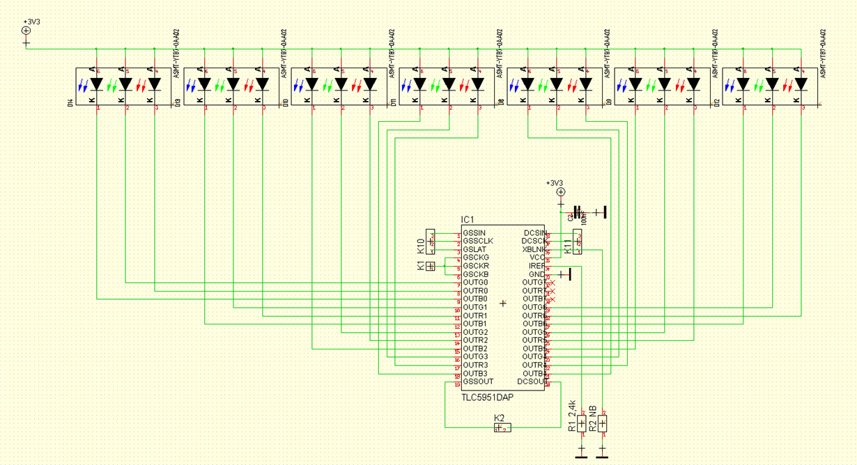
    yes, GSCKR, GSCKG and GSCKB use the same signal.  Attached you can find the circuit diagram of the 217 LED-Boards.

    Can you explain what the BIT195 and the BIT196 of the DC-signal really do? The explanation in the datasheet is for me not understandibly respectively it makes no sense.

    Best regards

    Franz Peter

  • Hi, Franz,

    For BIT195, it's used to enable/disable Auto display repeat function. If enabled, there is no need to use XBLNK to set GSCKR/G/B counter every 4096 GSCLK(12-Bit Mode for example). You can refer to Figure 43 and compare it with Figure 41/42.
    For BIT196, it's used to enable/disable Display timing reset function. When enabled, it's just like a low pulse of XBLNK is input and will reset GS counter to '0' at GSLAT rising edge.
    The XBLNK signal is not needed to control and can be connected to VCC when the display timing reset or auto repeat is enabled.

    Thanks.

    Regards,
    Kenneth
  • Hi Kenneth,

    in my application it works in this way:

    Sending RGB-Data (GS-Data):  XBLNK and GSLAT is put to low. Then the GS-data are send to the TLC5951. Then GSLAT is put to high for round about 8µs and again low. After that, XBLNK is put to high.

    For sending Brigthness-Data (DC-data): XBLNK and GSLAT is not changed; only the DC-data are send.

    I have tried different settings for BIT 195 and 196 - nothing was changed. It is always the same behaviour: if RGB(GS-Data) are not 0 or 4095 - it flashes!

    Why an Auto-display-repeat-function is needed? For what is it? What can I do with it?

    Why an Display-timing-reset-function is needed? For what is it? What can I do with it?

    Best regards and thanks so far for your patience

    Franz Peter Zantis

  • Hi, Franz,

    You can refer to the following thread for details about the Auto-display-repeat-function / Display-timing-reset-function :
    e2e.ti.com/.../100240

    You didn't use GSLAT after 288 GSCLK to latch Brigthness-Data? Please refer to Figure 11 and compare your signals.

    If it still flashes, you'd better analyze the OUT waveforms to get the flash frequency and compare with other input signals to determine which signal is not sent correct.

    Regards,
    Kenneth