This thread has been locked.

If you have a related question, please click the "Ask a related question" button in the top right corner. The newly created question will be automatically linked to this question.

TPS92075EVM: Current waveform & settle time

Part Number: TPS92075EVM

I have a few questions.
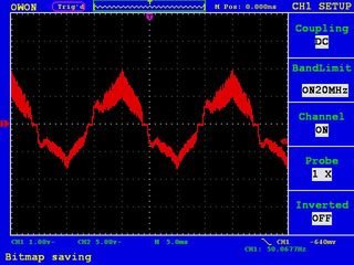
1. Because the chip is a PFC driver the ideal current waveform would resemble a sine, whilst on this board it looks more or less like a triangle (chip being settled). Is this the best PFC waveform I can achieve using that chip?
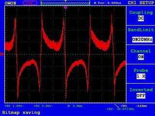
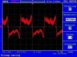
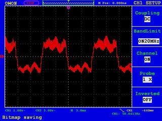
2. Settling of the chip takes about 2 seconds. Initially it is quite spiky then it transforms into a triangle (see pictures below). Does it meant to be like this?


Thanks.

  • Hello,

    Yes and Yes.

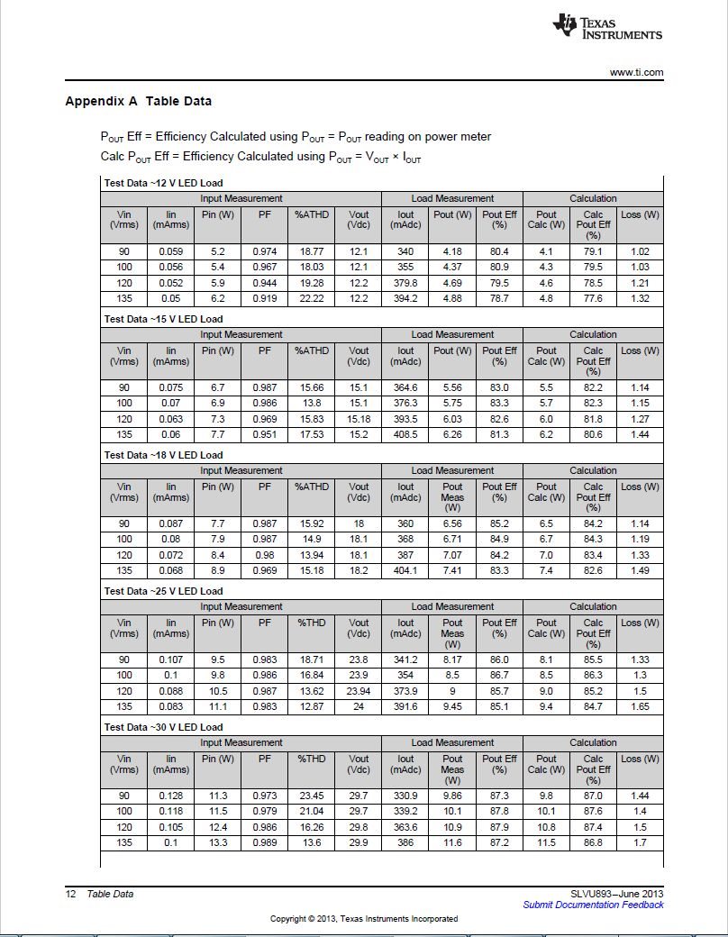
    1)  The TPS92075 has different modes of operation depending on what is sensed from the ASNS pin.  First it must sync to the AC line then determine the 'duty cycle' to determine if a dimmer is present.  If it does not detect a dimmer the reference becomes a triangle wave.  Power Factor with a triangle reference is actually pretty good.  If you look at the EVM data, below, at 120 VAC can be over 0.98.  Also note this is a buck converter so the higher the load voltage the larger the portion of the AC line that cannot pull current from the input.  Example, a 70 volt LED stack cannot be sourced using a buck converter unless the input is above 70 volts.  This means there is no current draw from the line if the rectified AC is below 70 volts.  This will affect PFC and THD.

    2)  Since the line frequency is fairly low and this uses digital sampling to determine what mode to be in it takes time to change states.  Your first scope picture is typical of a buck converter with a DC reference.  Since output power is constant the current draw from the AC line has to be higher when the voltage is lower hence the somewhat inverted sine wave look.  If you calculated point by point voltage times current the input power should be fairly constant over that waveform.  The transition from one mode to another is done over time so it is not an instantaneous change.  The datasheet explains this from about page 10.

    Thanks,

  • Hello,

    Is this possible to build a PFC driver using the TPS92075 that would maintain constant output in the voltage range 20-60V AC?

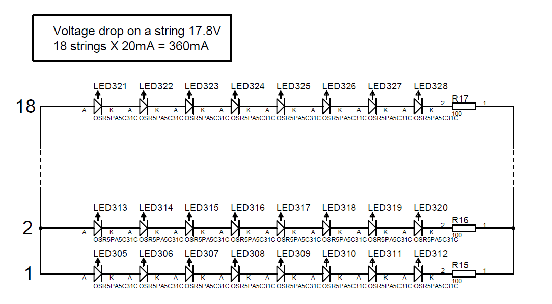
    The LED array has 144 LEDs in total. There are 18 strings, each consists of 8 red LEDs + 100R resistor, as it's shown in the picture below.

    Voltage across a string about 18V, total output current 360mA.

    Thanks.

  • Hello Piotr,

    TPS92075 really isn't meant to be a voltage regulator however in this instance I don't think you really want a voltage regulator.  If you have 18 strings at 20 mA, or 360 mA total I would set up the TPS92075 as a current regulator at approximately 360 mA.  It will provide much better light regulation than applying a constant voltage.  The resistors will help the strings share but the Vf of the LEDs will vary with temperature (and lot to lot from the LED manufacturer).

    If the string is 17.8 volts at 20 mA with 100 ohms in series the voltage applied would need to be 19.8 volts.  If the LED forward voltage drops 5% or 10% at elevated temperatures the current in the strings would jump to 28.9 mA and 37.8 mA respectively, or a 44.5% and 89% increase in current.  A current regulator just regulates at 360 mA so it doesn't notice the Vf change.

    Due to being PFC there will be a large ripple voltage on the output resulting in a large ripple current in the LEDs (depending on how large the energy storage capacitor is).  This is also true with a current regulator.  It requires the bandwidth to be very low, this is just how it has to work.

    Thanks,

  • Irwin,

    Thank you for your reply.
    Indeed, I meant the driver as a current source, not a voltage source. Sorry about not being precise.

    The question I wanted to ask was, if using that chip I can build a driver that would provide 360mA current to LEDs that would be constant at the input voltage range VIN 20..60V AC.

    Thanks.
  • Hello Piotr,

    It should work however the design would have to cover the 20 VRMS to 60 VRMS range meaning there is not much voltage available at 20 VAC input and it can only conductor for less than half of the rectified AC waveform (20*1.414 is the available peak voltage, 19.8V + 1V, output voltage and output diode voltage drop sum is the output voltage). It would be running from 47 degrees to 133 of the half sinewave (this doesn't include a rectifier bridge if you haven't). This means the switching frequency will vary a lot from the 20 Vrms input to the 60 Vrms input but more important the output current will vary quite a bit over that range. You may need to use a closed loop control with that range and output voltage, or, if Power Factor is not important, you could rectify the AC into a large storage capacitor and run from it. At this point it would be a DC to DC converter but not power factor corrected.

    You may be able to add an open loop circuit that somewhat compensates for input voltage. It depends on what your current regulation accuracy needs to be over that range. It will work but maybe not how you want it to.

    Thanks,
  • Irwin,

    Can you please tell me what you actually mean by the "open/closed loop control"?

    Thanks.

  • Hello Piotr,

    The TPS92075, without phase dimming, uses a triangle shaped reference for comparing the current sense to.  If a large portion of the input voltage is lower than the LED stack the converter in a buck converter current cannot be sourced to the LEDs.  This is an open loop control using off-time and peak current to regulate LED current.  This means the LED current average will be lower at 20 VRMS input than at 60 VRMS input.  You could use the TPS92075 as a buck-boost which would correct this problem though the efficiency will be slightly lower.  This part was designed for off-line applications where the input voltage doesn't vary all that much and, generally, the LED stack is much lower than the peak of the rectified AC.

    Closed loop uses an error amplifier and if Power Factor Corrected has a very low bandwidth to average the PFC input current which the LEDs regulate to.  It will, most likely, use a large capacitor for compensation making it an integrator.  If, in a buck converter, the voltage is reduced the available duty cycle for the input voltage to be higher than the LED stack is reduced.  In this case the error amplifier would increase the peak current so the average remains the same.

    Thanks,

  • Irwin,

    Thanks for clarification.

    Kind Regards,
    Piotr