This thread has been locked.

If you have a related question, please click the "Ask a related question" button in the top right corner. The newly created question will be automatically linked to this question.

TPS92075: Convert constant current to constant voltage?

Part Number: TPS92075

I have got yet another question.

Is it possible to alter the application from a constant current to a constant voltage mode? The reason why I'm asking is, we want to use about 138 LEDs in our product: 46 strings with 3 LEDs per string. Failure of one LED would result in the current increase in the remaining strings. This is undesirable for 2 reasons: 1) failure of an LED would put more stress on remaining strings, 2) input current of the driver would remain unchanged until the last string works. In our application the current drop is used to let the "external world" know there is something wrong with the light.

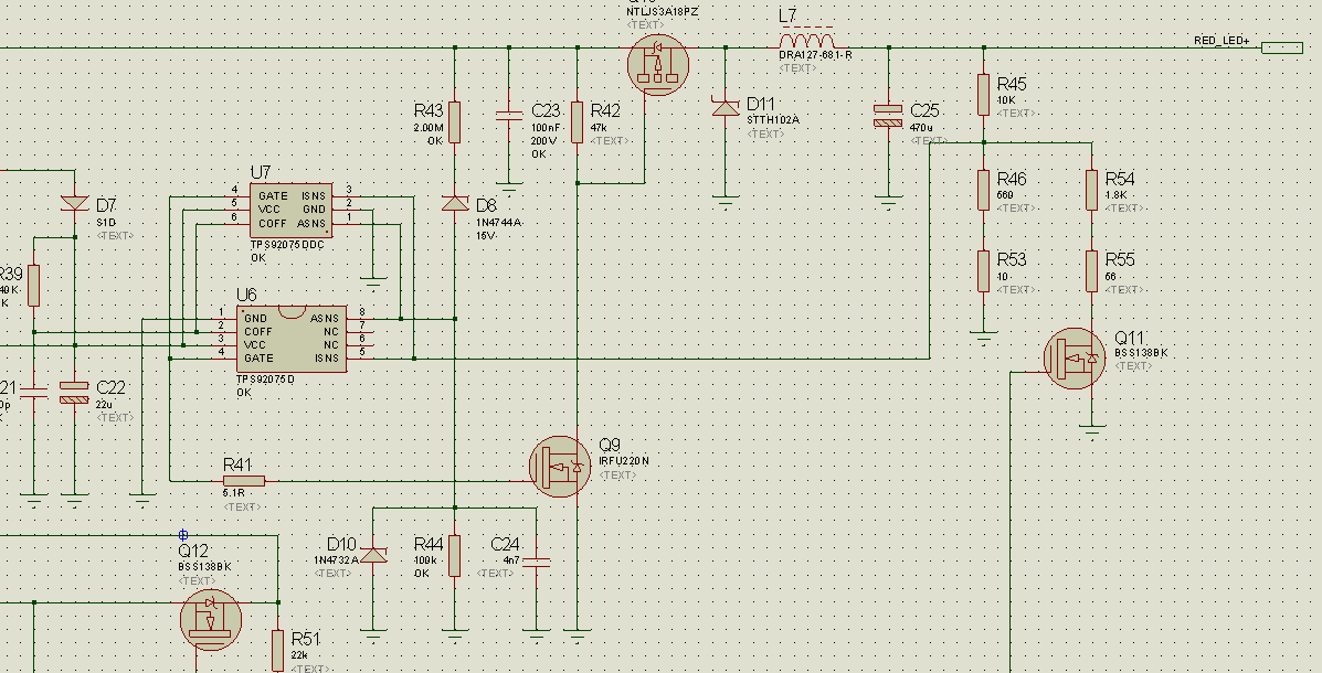
Below I attached an altered diagram of the driver. Please disregard values, as they have not been calculated yet. Mys question is about the topology that was changed to maintain constant voltage at the output (RED_LED+). Would this work?

Thanks.

  • Hello,

    It is possible but probably the wrong part to do this with.  As the schematic is it won't work.  If the MOSFET is on ISNS is looking for a current ramp to determine when to shut off the MOSFET, this doesn't provide a current ramp to ISNS.  I'm sure this is a preliminary schematic but you will also have issues with the highside MOSFET drive as it isR42 will make switching loss very high, the gate also needs to be clamped to prevent over-voltage on the upper MOSFET gate (so another resistor and a zener minimum) but to get a low impedance driver more would need to be added.

    The other issue.  If you have 46 strings of three LEDs each what limits the current in these strings?  An LED driver really wants to source current because of the variances in LED Vf and thermal drift.  Basically if you drive an LED string with a constant voltage it will, most likely, thermally run away unless something is limiting the current.  Also, if one string of 46 opens it won't be detectable unless looking for a step change in the output current, even so it is near a 2% change, hard to detect.  If each string has a reasonable value series resistor it can work though the efficiency will be affected.  The resistor can also be used to determine if the string opens.

    What is the current in each LED string, total output power and anything else that helps understand the intent of the design?

    Thanks,


  • Irwin,

    Many thanks for your reply.
    Regarding your inquiry, our goal is to build a light signal using 138 high intensity LEDs in total. There are 46 strings with 3 LEDs and a 270R resistor in each string. The driver input voltage ranges between 20 and 60V AC.
    Voltage across a string is 12V, current of each string equals 21mA.

    All strings are connected in parallel for 3 reasons:
    - Voltage drop across a string is about 12V that allows the light unit to work at a very low input voltage.
    - Failure of a single LED turns off only 3 LEDs. If this happens the power consumption drops down and an external monitoring unit “knows” that the light is malfunctioning. This is why a constant voltage driver is required. For the same reason Zener diodes across each LED to minimise “holes” in the LED array in case of an LED failure must not be used.
    - Such an LED topology is intentionally energy less efficient and draws more power from driver (comparing to a single LED string). The reason for that is a minimum wattage of each light that should be about 10W.

    Thanks,
    Piotr
  • Hello Piotr,

    A few more questions:

    Does this need to be power factor corrected?  Or can it just be bridge rectified and then converted to 12 volts?

    Does the output need to be isolated from the input?  (Flyback versus buck or buck boost, etc.)

    Is there any safety/compliance items that need to be taken into account such as surge protection, isolation (due to voltage safety, 60 VAC is above a 'safe' voltage), etc?

    Thanks,

  • Irwin,
    We have just decided to build a standard PWM buck converter. Although the PFC would be a merit, it is not required.
    It does not have to be isolated, but the surge protection is essential.

    We have already got a solution.
    Many thanks for your help!

    Kind regards,
    Piotr