This thread has been locked.

If you have a related question, please click the "Ask a related question" button in the top right corner. The newly created question will be automatically linked to this question.

LM3421: Issue when dimming at 20KHz, DCM mode appears and dimming cannot be performed

Part Number: LM3421
Other Parts Discussed in Thread: LM3431, , LM3423, TPS92515

Hello,

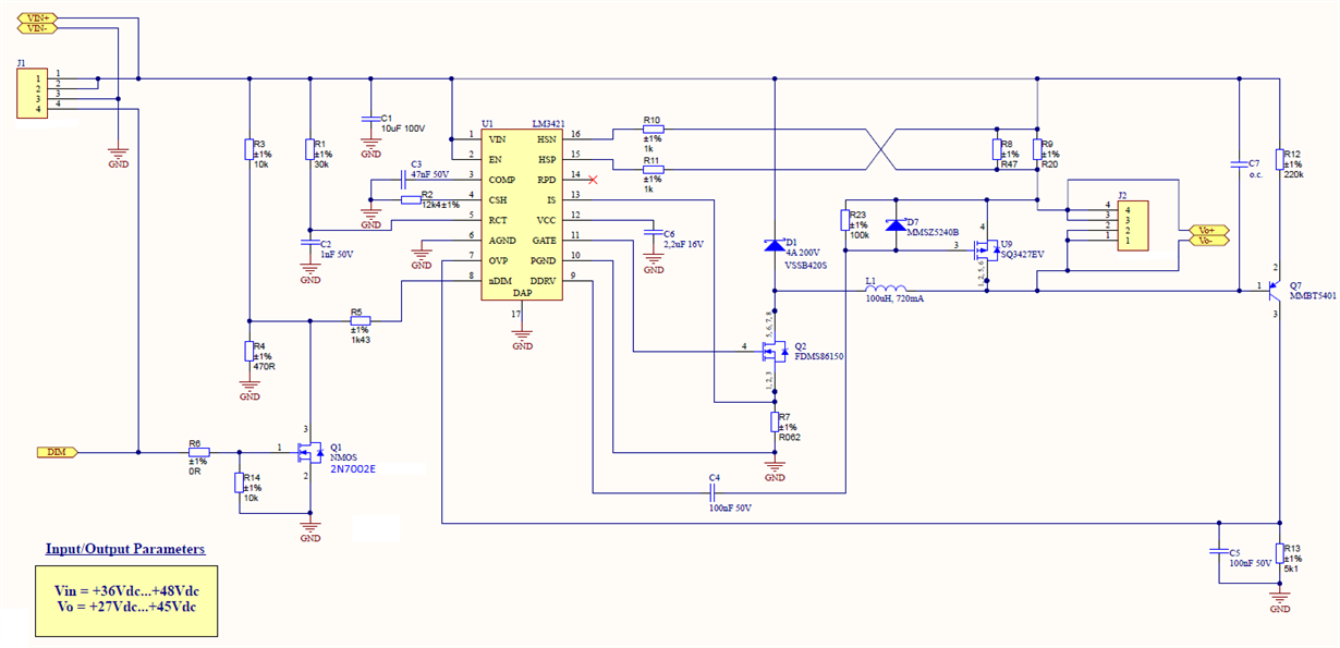
I am having problems with LM3431 configured as Buck Converter to drive leds at 700mA when dimming. I attach you the schematic for your perusal.


I have designed it following the guidance included in the datasheet of this controller and it works really fine when it is used in fixed current. The output current is set up at 700mA and it remains without changes for the full range of the input voltage (from 36 to 48V).

In fact, if I change the output load from 9 leds (Vf = 3V each, so I have 27V approx.) to 15 leds (Vf = 3V each, so I have 45V approx.) the output current keeps in the expected value (700mA) and the converter is really well adjusted.

The issue appears when I change to dimming mode and I connect a 5V to 10V digital input voltage to the LM3421 through the mosfet input that manages the input for the dimming purposes.

After testing stage, for frequencies that goes from 1KHz to 10KHz works fine and the lineality is acceptable and accurate. But for frequencies that goes from 10KHz to 20KHz and specially for 20KHz I have detected that the dimming cannot be performed well and the Buck set up the DCM mode until a minimum of 40 or 50% is reached. This is more perceptible when I have got much difference between input and output (48Vinput and 27 output is more sensitive than for 36Vinput and 27Voutput).

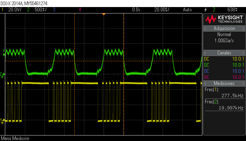
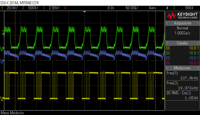
I mean, when I change from 100% to 0% the dimming seems to be correct, but when I try to increase from 0% to 100% it only works sometimes if I increase slowly the dimming steps (I have always done this by steps of 1%, i.e.: 0%, 1%, 2% and so on). After this "slowly-start", so to speak, I can reach 100% without problems. I attach you a picture after a "slowly-start" with 50% dimming signal.

Ch1: Vsw at node, Ch2: Io


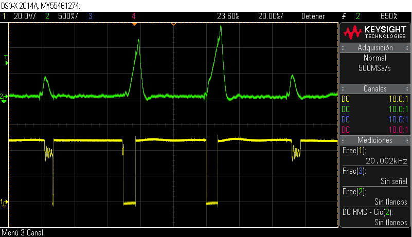
On the other hand, If I speed up the dimming step and I do it faster (I do it moving faster the rolling button of the function generator connected to the mosfet), DCM mode is stablished and it dissapears when I reach 40% or 50%, approximattely. Here, you can see the Isw output current (CH2) and the Vsw (CH1) at switching voltge node.


I cannot understand why this happens because the datasheet specifies that for Buck converter PWM dimming can be up to 20KHz or even more.

Is there any problem between frequency switching and frequency for dimming signal? Which is the limit for the frequency of the dimming signal when I set the frequency switching?. Does the Cdim and RPU component values have to change for fixing it?

It seems as if the LM3421 would not accept fast dimming step changes for 20KHz. It does not occurs for the rest of frequencies.

Thank you all in advance. Hope you can help me because I have tried to increase frequency switching signal and I am still with the same problem.

Regards.

  • Hello Aaron,

    I'll try and help out, the expert on this part is out until next Monday.  I noticed in your last oscilloscope picture that the switch node is actually not fully turning on.  The current also seems to be going higher than it should when after the MOSFET on-time.  Also when starting from zero the compensation voltage may not be where it needs to be.  Can you look at the compensation voltage for correct and incorrect operation?

    If the input is at 48 VDC versus 36 VDC the current will ramp up quicker since the applied voltage to charge the inductor is 48V - 27V = 21V versus 36V - 27V = 9V.  I noticed you do not have the Cfs and Rfs on your schematic which helps filter switching noise.

    Is your inductor rated above 720 mA?  It needs to have enough margin for the ripple and all operating conditions.  It looks like your ripple is about 120 mA peak to peak and your switching frequency is approximately 833 KHz.

    Have you looked at Vin to make sure it is stable?

    Regards,

  • Hello Irwin,


    Thank you for replying replying so quickly!.

    First, I have tried to increase the fsw until 700KHz just to see any dependecy with frequency dimming, but after the test I just got higher temperature in the main mosfet Q2 as it was expected. I got the same result as before.


    As for your tips and suggestions:

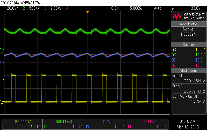
    1. What is expected to see in the comp pin? I only see a voltage that seems to be quite normal, despite a bit off noise, but I think is normal and does not make an undesired behaviour. I attach you to captures, the first one is for fixed output current and the second one is for 20KHz dimming signal at 50%.

    Ch2 = Io, Ch3 = comp pin (pin 3), Ch1 = Vsw.

    2. I am aware of you talk about the current ramp depending on the voltage-ratio (Vin-Vo). That is the Ohms law applied in an inductor for a Buck converter. I agree with you but I do not think that this would be an important restriction to get the desired behaviour for 20KHz dimming. I have also see in the datasheet of the LM3421 (page 57, SNVS574F-JULY 2008 REVISED july 2015) a similar circuit developed for LM3423 which input voltage range is from +15Vdc to +50Vdc and the output is 9V (3 leds, vf = 3V). Here, the PWM dimming is specified up to 50KHz and as you can check the voltage-ratio applied to the inductor is higher than the one I have got in my design.

    Another important aspect I want to talk about is regarding Cfs and Rfs. I do not have assembled them in my circuit and I have never see them in assembled in other Buck converters implemented with LM3421, either. That not means it should not be used anymore, but according to my design which follows the guidance, I have tested with Cfs = 8.2 nF and Rfs = 10Ohm and the full behaviour is not been affected.

    So I conclude that this has not a direct impact on the purpose of 20KHz dimming. Maybe I am wrong...if you could help me anyway, it would be nice!...That is why I am asking for some advice on what to do.

    3. The inductor is designed taking into account that the ripple should be no more than the 30% of the rated ouptut current. That is a rule of thumb for Buck converters design as for my experience and I also saw this recommendation in the page 26 of the datasheet (you can see that the value specified here is to be less than 40%). Therefore I got a 100uH inductor which has 720 rms current and 1.1A for Isat. I do not have problems, or at least I think so, with the inductor and it seems to accomplish the current ripple well without being too hot.

    I have tested the input voltage and it seems to be Ok.

    I summary, everything seems to work fine until I try to appluy a 20KHz dimming signal, after that, input voltage is affected by thisDCM mode, comp pin seems to be wrong and everything is then operating bad until I reach 40% or 50% as I have mentioned before. I cannot explain what is going on?

    And finally, I tried to add an output capacitor (i.e.:10uF to 1uF and even 100nF) to reduce a bit more the ripple in order to check if that could be the problem. After testing it, I saw that the converter started a bit faster and when I connected the 20KHz dimming signal, the converter switched off because U9 (dimming transistor) reached an high temperature very quickly and an internal  protection seemed to activate then. It was curious, but I actually can't add any output capacitor due to this fact. I think that I do not need anyway because a buck converter with current control can operate without output capacitors when a led is used as a load, but the fact is that I cannot use them.

    So I hope we could fix this problem because is very important to me.

    Thank you all in advance.

    Regards.

  • Hello Aaron,

    We can look into this further next week if needed. But maybe increasing the bandwidth could help. 47nF for a COMP cap may just not be fast enough to react to the dimming since it is a buck with shunt FET dimming. Maybe you could try reducing Ccomp to 10nF or so to see if there is improvement?

    One other thought is that there are other converters that specifically buck converters that are much faster in general. Have you considered the TPS92515 for this application?

    Regards,

    Clint

  • Hello Clint,

    First, I would like to clarify that the signal shown in the Ch3 belongs to pin 4 (CSH) and does not correspond to pin 3 (COMP) as I had typed. An erratum, I am sorry.
    The signal at pin 3 (COMP) is a continuos signal as I have said before.

    As for TPS92515, maybe it is a good solution but LM3421 driver is a customer requirement, so we have to work with it, unless we finally check that it is not suitable.

    Getting back to my design, let me to explain why I have proceeded in such a way. C3 must be 10.8nF but I never used that value and I adjusted to 47nF just because I have several set up that goes from 0,2A to 0.9A. So, C3 goes from 8.4nF (0.9A) to 38nF (0.2A). I tested with 47nF for 0.7A and seemed to work fine until I tried 20KHz dimming signal. For fixed current I always got an almost perfect output current control regulation (1%, approx.).

    I tried to change the value of C3 (comp capacitor) to check whether I could get any improvement and I got it. The fact is that reducing this capacitor the LM3421 reacts better to 20KHz dimming signal and is well performed and a bit faster, maybe not as much as I need due to my customer requirements, but is faster than before.

    Finally, I chose 22nF which allows correct functionaility for al the input voltage range (36V to 48V) taking into account output voltages from 27V to 45V, as I have already detailed before. If I reduce C3 more, dimming is not well performed at 20KHz when I have got a load of 30V (10leds, Vf = 3V each) or 33V (11 leds, Vf = 3V each) and I finally get the same problem (DCM mode and so on...). I have also noticed that to choose a suitalbe CMP capacitor when the load (number of leds) is changeable is not easy and impacts directly in the PWM dimming frequency used. Could you please explain me a bit more about this? This would help me to understand how to adjust better my future designs with LM3421.

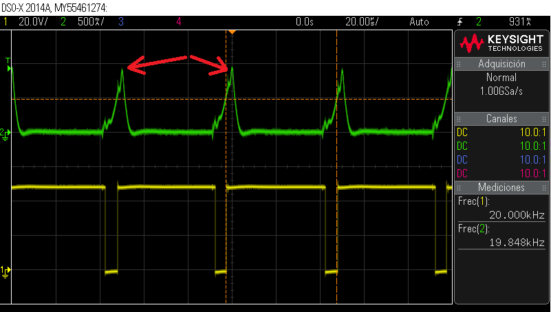
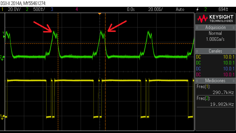
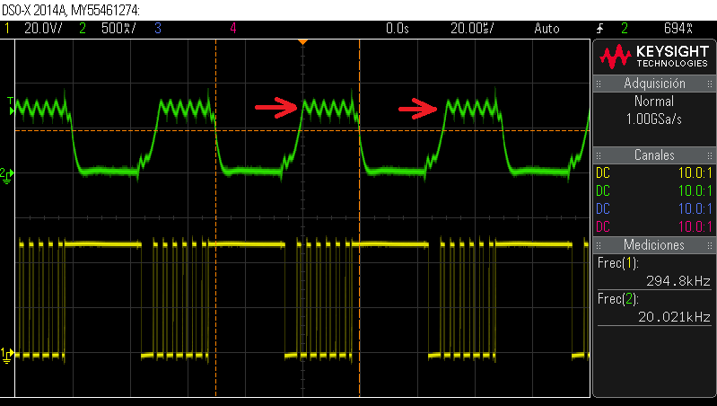
    Just one more thing that I am watching all the time for any of the dimming frequencies used, (1KHz to 20KHz). When I start to increase PWM duty cycle, the current ramps up to a certain peak value and then slows down a bit as PWM duty cycle increases. The result is that you can see a peak ramp and then the output current ripple in a lower level, so to say. This is then reflected on the leds and consequently the effect is amplified if the PWM duty cycle change is performed fast at starting time. I attach you some captures (left arrow is pointing the peak ramp and the current ripple that follows).

    Ch3 = Io, Ch1= Vsw node.


    Is there any possibility to get a soft-start output current when dimming?. For fixed current mode I do not have this problem.

    Thank you very much for your tips and suggestions!.

    Regards.

  • Hello Aaron,

    This makes much more sense now, especially since changing Ccomp made a difference. What is happening is that the pulse width is getting short enough that the COMP pin voltage can't quite settle to its regulation point. That is why increasing bandwidth can help. When the pulse gets too short for COMP to react it can go higher than you would like and/or oscillate then it will disconnect with the PWM signal so that the next on cycle it's at a higher or unpredictable level.

    If you need to PWM dim at such high frequencies it may require different compensation for different conditions. Either way there will be a minimum duty cycle before this is a concern. But one other option regarding your "soft-start" comment is to connect a resistor (maybe 250k to 2M) from COMP to ground and it can discharge COMP a bit so that the next cycle the peak isn't so high. We have had success with that in the past.

    Regards,

    Clint

  • Hello Clinton,


    Thank you for your comments again, really useful and profitable.

    I have connected a resistor of 330KOhm according to your recommendation and now it really works fine (soft-start) when I start to dimming and there is no problem at 20KHz or 10KHz.

    I would like to thank you and TI team, for your quick attention and your accurate reply.

    Regards.