This thread has been locked.

If you have a related question, please click the "Ask a related question" button in the top right corner. The newly created question will be automatically linked to this question.

TPS7A4700 and TPS7A3301 not regulating correctly

Hello, I am trying to implement TPS7A4700RGWT and TPS7A3301RGWT linear regulators in to a new PSU design. I have prototyped both ICs with little success. I will talk specifically about the positive regulator from here on. My schematic is as follows:

http://snag.gy/cIeru.jpg

This should attain a +12V output. I built this circuit up as depicted, but the regulator provides no regulation. The output voltage tracks the input voltage (minus a few millivolts). I was concerned the layout I used was the problem so I deadbugged the circuit with a new chip, and exactly the same problem occurred. I replaced R1 and R2 with a 100K pot, the wiper connected to the FB pin. As I varied the potentiometer, the voltage output started at about 1.4V, climbed to ~2.5V then snapped to maximum voltage output - well before the potentiometer had finished rotation. I tried using the digital control pins to vary the output voltage which did in fact work - but my design calls for very clean +ve and -ve rails, the negative part does not have digital control lines. When I try and implement the negative regulator - it does regulate voltage but the output 'wobbles' ~+/-100mV slowly. Lowering the recommended resistor value helped this problem slightly but it did not cure it. Are there a bad batch of regulators out at the moment? What could I be doing wrong in implementing these devices? Any help is greatly appreciated

Thanks, Dan

  • Hi Dan,

    I was unable to view your schematic.  Could you try and insert it into your post?  Also, would it be possible to provide scope shots of the input and output voltage?

    Very Respectfully,

    Ryan

  • Hi Dan,

    I have also similar problem.
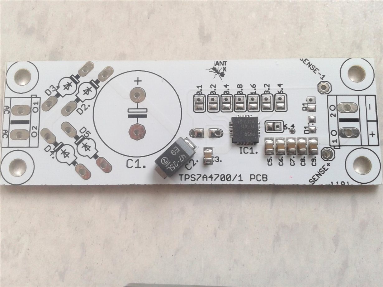
    I made Tps7a4700 regulator on well made board from diyaudio forum.
    I have one problem, under load or no load after start up, voltage is 20% higher and slowly drops to selecable volatge...
    For example ...i connect pins for 3,3V output and when i start it up, voltage is arround 3,8-4V ...i built 5 of them and on every board ist the same problem. When i touch or make conntact on 1uf Noise capacitor the voltage drops to right value 3,3V, when i put my finger of the cap away voltage gets to 3,6V .... and slowly after some minuts drops to around 3,3V. I have tried 10nF or 100nF ...no big difference. Noise is no problem ist almost umesurable with my scope.
    www.diyaudio.com/.../263618-tps7a4700-low-noise-ldo-regulator-pcb.html
    Thank you
    Davorin
  • This issue should be directed back to mravica at the diyAudio forum as this does not appear to be a TPS7A4701 problem. Request a Users Guide, or errata sheet, for your power supply that explains the options.

    From the schematic at diyAudio, and your description of behavior, I can only guess that the TPS7A4701 SENSE/FB pin is not connected to the + output. Try shorting SJ9.

    Also, short SJ10 in order to connect the NR capacitor to Gnd, this will allow for soft-start to reduce possibility of output voltage over-shoot at power-up.

  • Hi Davor,

    One more thing on top of Don's - make sure you are using the TPS7A4701, not the TPS7A4700. The TPS7A4700 only has a SENSE pin, not a FB pin - using a divider network in front of the SENSE line can cause some issues.

    Regards,
    David
  • Hi David,

    Oh yes mea culpa, my mistake, i have used 4700, what should i changed in that design to work properly.

    Thank you very much

    Davorin

  • Good point on the difference between the two '00 vs '01.

    I'm not seeing anywhere in the documentation at diyAudio (in the schematic, or on the pcb) a place to add R1 & R2. 

    The diyAudio web page clearly lists the " ... TPS7A4700 single voltage output ..." 

    I'll guess that the schematic is not properly labeled (i.e. '01 should be '00) and circuit is intended for the '00 device only.

  • Hi D
    You are right, it ist just ANY out possibility, no resistor adjusting is possible. It is no need to in audio power supply designs . We mainly need 5V 3,3V and +/- 15V . It is not problem in that way. It is only NR capacitor problem. After startup is overvoltage and voltage immediattely drops when i touch smd x7r 1uf NR capacitor with fingertip. I am afraid to damage DAC because AVCC is max 5,5V and after startup is 5,8V and DVCC 3,3V at startup with just resistor load 3,8-4V.
    Thank you
    Davorin
  • So, back to the two suggestons :
    1) make sure the Sense pin is connected to +Output, and make sure the NR cap is connected to Gnd. I don't see silk screen labels on the pcb for the NR capacitor (aka C4) or the two solder jumpers (SJ9 and SJ10), so I can't draw a picture with 100% certainty. but it appears to me that both SJ9 and SJ10 are on the bottom side of the pcb. This is the kind of details that would be in a Users Guide.
    2) if #1 above doesn't fix/help your problem then go back to mravlca at the diyAudio forum.