This thread has been locked.

If you have a related question, please click the "Ask a related question" button in the top right corner. The newly created question will be automatically linked to this question.

Boosting output current of Linear Regulator TPS7A4701

Other Parts Discussed in Thread: LM3466, TIDA-00270, TPS74401, OPA333

Hi All,


I'm just needing some basic direction in how to pass more than 1A for this chip. I need ultra low noise at approx 3A but perhaps as high as 5A (at 12VDC).

So far I have not got the development board, however I assume I need to add to the design a pass transistor across the output to get the higher current?

  • Hi Martin,

    Unfortunately any method to boost the current on the output of the LDO will introduce a new noise path and degrade the noise performance on the output rail.

    As noise is a concern for you, one thing you may want to try is paralleling LDOs with a ballast resistor.

    Very Respectfully,

    Ryan

  • Hi Ryan,


    I understand the issue and the suggestion sounds plausible however I would like to know if a device (like a LM3466) could be used instead of and inefficient or suboptimal Ballast resistor solution. I know this item is not the likely right solution however some form of active current balancing must be available?

    Regards,

    Martin

  • Hi Martin,

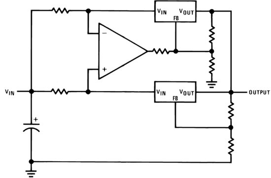
    You could look into using an op-amp to do current sharing with LDOs.  We are in the process of releasing a reference design based on this circuit.

    Very Respectfully,

    Ryan

  • Hi Martin,

    We have released the design that mentioned in the previous post.  You can find it here:

    http://www.ti.com/tool/tida-00270

    Very Respectfully,

    Ryan

  • Ryan -

    If I'm not mistaken, this looks easily scalable in powers of 2,.  You have a left and right pair that are compared, then the total of that is compared by a third amp.

    Lets talk noise. I have a 24VDC 2.2A application involving high energy oscillators.  Noise matters, greatly.  The TPS7A4700 has record low noise up to 800ma (or so) of 3 or 4 uVrms, right?  If I had 4 plus the other circuitry here, how much noise are we thinking?  

    Most even 1.5A LDOs are in the 30-40 uVrms range - so we have a 10x multiplier to work with here really.  

    NS

  • Hi NS,

    In the Test Data report for the TI Design we show noise plots of the paralleled solution that are consistent with the EC Table of the individual TPS74401 datasheet.  As such we would expect noise to be similar to the individual device.

    Very Respectfully,

    Ryan

  • Hi Ryan

    Can you check if it is possible to have similar design for TPS7A4700 in "ANY-OUT" mode (without resistors connected to FB input)

    BR
    Alex
  • Alex,

    You can do it with the ANYOUT resistors but you must make sure that you are not connecting the pins together between the two devices. For example, if you are not grounding the 0P8V pins, they should not be connected between devices; connecting them will create a floating node situation that will affect the output voltage.

    The output of the amplifier will need to be tied to the SENSE pin. However, since you are using ANYOUT, you will not be comparing against 1.4V, the reference voltage with the conventional resistor divider, anymore. Instead, you need to drive the SENSE node at whatever your LDO output voltage is. If your output voltage exceeds 5.4V, you will have to use another amplifier to output that voltage. You will also need to adjust the resistor at the output of your amplifier accordingly.

    Having said all this, it's much simpler to use the external resistor divider since you don't need to worry about any of the aforementioned details. 

    Let me know if this helps,

    Aaron. 

  • Hi Aaron

    Really appreciate your support, but in my case i have few limitations
    1. I have a small PCB with TPS7A4700 installed (with Enable, Vin, GND, Vout and Sense PINs) and soldering pads for voltage selection - so, i am unable to use external divider, even outside the board (as i understand it is possible only with 7A4701 only).
    2. I want to keep same noise level as Single VR.

    Lest assume that we have master LDO with Output voltage programmed by ANY-OUT pads. My idea to have an external circuit, which can measure Output voltage of Master LDO and Voltage drop on external input resistors (like R1/R2 here www.ti.com/.../tida-00270) and drive sense input of slave VR in order to make equal current draw for BOTH VR, i believe in this case (equal current for both VR) output voltage of slave LDO will be same as Master, and output voltage of Slave VR will NOT depend on ANY-OUT settings of Slave regulator

    BR
    Alex

  • Alex,

    Per TIDA-00270, you'll have to sense current at the inputs of each LDO with the OPA333. Like you said, you can set the master output voltage with ANYOUT pins and leave the ANYOUT pins floating for the slave device. The OPA333 output should be connected to the slave SENSE/FB pin. You might need to adjust the resistor at the output of the op-amp to ensure there is enough swing.

    ~ Aaron