This thread has been locked.

If you have a related question, please click the "Ask a related question" button in the top right corner. The newly created question will be automatically linked to this question.

LM317 unexpected transient behaviour

Other Parts Discussed in Thread: LM317

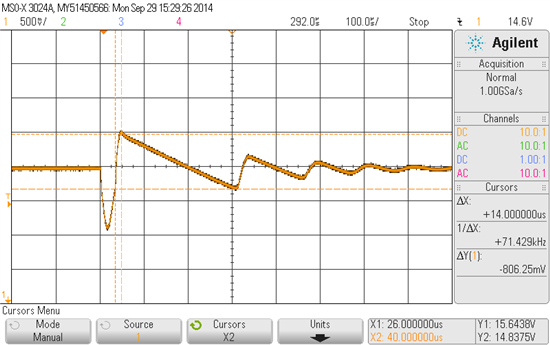
We have an existing design using an LM317 with 24V in and 15V out. There is lots of input capacitance and 10u and 100n on the output. The Adjust pin is connected only to two resistors to set the output voltage. We have a 1Kohm continuous load and a switched 330mA load which is on for about 40us every few ms. We see a negative excursion to about 14V when the load switches on, then a positive excursion to about 15.5V at turn-off. So far, this is all expected. The 1K load causes a slow, linear discharge from 15.5V, which is different from the data sheet transient plots, but not surprising with light load and the output capacitance. The surprise comes when the linear discharge continues for about 300us, past the set-point and down to about 14.6V. Then there is another sharp positive edge, up to about 15.2V, and the slow, linear discharge starts again. This happens for about 6 cycles with each one being smaller and shorter than the previous, until the output settles at 15V, until the next load transient. This is not ringing any any normal sense, but an apparent switching behaviour in a device that should be linear. We can not explain why the regulator does not respond when the output decays to the setpoint, but waits for more than 100us, and then switches on, rapidly charging its output capacitor and overshooting again.

As a test only, we added 10u to the Adjust pin, and the unusual behaviour was mostly gone. We do not understand how transient response can be improved by adding phase delay to the feedback path. Unfortunately, this is a complex board, and it is difficult for us to just add this component. Right now, we are just trying to understand what we are seeing.

  • Bruce,

    The repeating pulse pattern is indeed ringing. Systems with vastly different source / sink capabilities will ring or oscillate with a saw-tooth wave shape (unless the amplitude is very small).

    The cap from adjust to ground is not a lag network. The LM317 feedback is ADJ to OUT (not ADJ to ground).
    The 100nF output capacitor will have a stable loop, but it will have a predictably low phase margin. 
    Removing the output cap or increasing it will provide a higher phase margin.

  • Thanks Ron. This helps, but we are still puzzled that the 317 output drifts slowly through the set-point and continues to fall for more than 100us, without the regulator doing anything. We couldn't see anything in the LM317 schematic that would account for this long delay (of course, we don't know how big the internal capacitors are).

    In our application, the output of the regulator has 10u+100n in parallel, so we are a long way from 100nF.

        Bruce

  • Bruce,

    From the schematic, I see that the output NPN Darlington output going into a hard cut off will remove power from the band gap (PNP mirror) and add negative charge to the band gap output capacitor. I believe that could take a finite time to recover. Once low voltage is detected, over correction takes place.

    Is this causing a problem?
    Is the 10uF capacitor ceramic?

  • The output capacitance is actually a pair of 4u7 ceramics with enough headroom to really be that value (i.e. they are 50V parts). The circuit which creates the load transient is not active after the transient, so it doesn't care about the disturbance. Another section which uses the 15V is active all the time, but it is remote (end of a cable) and it has a local LDO further reducing the 15V to 12V, so it is not affected either. This question was more to try to understand something we could not explain. Thanks for your help in this. I will study the chip internals based on what you explained. We will add the Adjust pin capacitor at the next board spin. In our testing, it seems that 100n works as well or better than 10u at that location (set resistors are 274R and 3K01 so 251 ohms impedance at the pin).

    Thanks Ron!

    Bruce