This thread has been locked.

If you have a related question, please click the "Ask a related question" button in the top right corner. The newly created question will be automatically linked to this question.

TPS7A4901 & TPS7A3001 – About usage

Guru 21045 points
Other Parts Discussed in Thread: TPS7A30, TINA-TI

Hi Team,


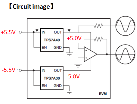
Our customer are evaluating TPS7A4901 & TPS7A3001 at the following condition.

However, the click noise occurs from the audio amp.

According to our customer, it is caused by the fact that TPS7A4901 and TPS7A3001 do not startup at the same time.

Therefore, they would like to know the method to solve this problem.


[conditions]

Vin=5.5V => TPS7A4901 => Vout=5.0V / Iout=150mA

Vin=-5.5V => TPS7A3001 => Vout=-5.0V / Iout=150mA


I’m understanding that we can change the startup time to change the soft start capacitor.

Could you please let us know if you have any idea?


And, have you received a similar question?

Could you please let us know if you have other recommended device?


Regards,

Kanemaru

  • Hi Kanemaru,

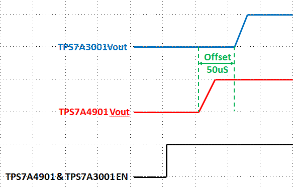
    I've actually looked into this while working on some issues with start-up time on op-amps and data converters. The easy solution is to increase the sizing of the NR capacitor and slow down the ramp rate on the input - try using a 100nF+ NR capacitor on both parts. This won't give the same start-up time but it will force a ~100ms start-up time while the offset between the two parts starting up (from EN) is around 50us.

    Regards,
    David
  • Hi David-san,


    Thank you for the information!

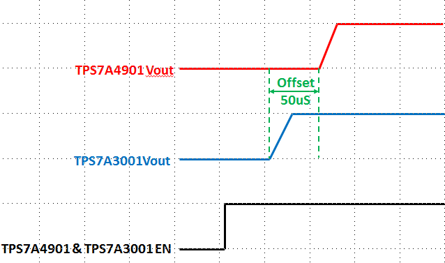
    I’m understanding that “the offset between the two parts starting up (from EN) is around 50us” is the following image.

    Is my understanding correct?


    And, I have one more question.

    According to the datasheet, the recommended value of CNR/SS is 0.01uF(=10nF).

    Do the noises increase if we use CNR/SS=100nF?


    Regards,

    Kanemaru

  • Hi Kanemaru,

    You are correct - the measurements I've done show it is around 50us. However, the negative rail will start first and the positive will follow it.

    Using a larger NR capacitor will decrease the noise.

    Regards,
    David
  • Hi David-san,


    Thank you for your prompt reply and your advice!

    I understood about following contents.


    And, I found the calculation method of the soft start time(tss) at TPS7A4901 datasheet.

    However, I can’t find this calculation method at TPS7A3001 datasheet.

    I’m understanding that the soft start time of TPS7A4901 and TPS7A3001 can calculate by same calculation method.

    Is my understanding correct?

    If no, could you please let us know the calculation method of the soft start time of TPS7A3001?


    Regards,

    Kanemaru

  • Hi Kanemaru,

    Actually for the TPS7A30 the equation is tss(ms) = 0.9 * Cnr/ss(nF). The datasheet is currently being updated with this information.

    Regards,
    David
  • Hi David-san,


    Thank you for your prompt reply.

    I will report this information to our custoer.


    Regards,

    Kanemaru

  • To follow up on the above remarks, it'd be helpful if the 50us offset and Cnr soft start could be included in the TPS7A4901 and TPS7A3001 transient Spice models so they're more correct in indicating behaviour.  I've also noticed that, in addition to including nonfunctional NR pins, the models appear to have zero reference noise.  (And why are these parts under SMPS Spice macros in TINA-TI?)

    As this is a general thread on the regulators' use it seems worth remarking 10uF X7Rs typically derate about 85% at 35V.  This implies the EVM falls below the 2.2uF minimum Cout recommendation on these parts at high Vout.  The EVM fails also Cin recommendations in all conditions as 1uF parts are used.  Cnr and Cff look a bit of a tumble too.  The datasheets are written as if 10nF is optimum whereas this thread suggests an order of magnitude increase in Cnr and documents referenced from the datasheets advocate up to three orders of magnitude larger Cff.  If one follows the Fz guidance located at the end of this thread R1 and R2 selection admits three orders of magnitude.  That's about seven orders of magnitude of parameter space to select from.

    Would be helpful if such contradictions, ambiguities, and omissions in the design collateral could be reduced.  It's been unnecessarily interesting identifying what to try on the bench.