This thread has been locked.

If you have a related question, please click the "Ask a related question" button in the top right corner. The newly created question will be automatically linked to this question.

LM337IMP Output Has 180mV Sawtooth Ripple

Other Parts Discussed in Thread: LM317, LM337, LP2950, LM337-N

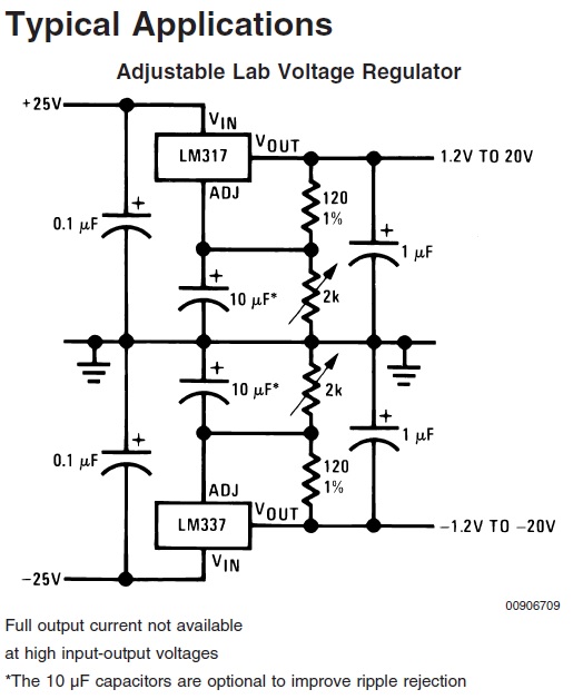
I have used the LM317 and LM337 regulators many times in this configuration. In this case the LM337 output is set to 9V. Superimposed is a sawtooth with 180mV amplitude. The frequency and amplitude are affected by the amount of capacitance connected to the output. The sawtooth remains even after disconnecting everything. Even the output capacitors were removed one at a time. The adjust pin was grounded to eliminate the adjust to ground capacitors and resistor. The sawtooth is still present even though the output is at 1.25V. Schematics, output waveform and board layout attached. The regulator does not get warm. It has been replaced twice with parts from different date codes and manufacturers (TI and National).

  • Hello Scott,

    Looks like you covered a lot of bases.
    Thermal overload, adj pin oscillation.
    So you mentioned that you tried different devices and found the same response?
    You also mentioned that you have used it many times in this configuration, have you had different results in the past with the same board?
    Also, you don't see oscillation on the input?

    The only other thing I could think of would just be instability of the regulator which might be caused by output capacitance. Typically these devices are stable with and without an output capacitor, so I find it strange if you have 12Vin, 120Ohm to ADJ/GND and you aren't seeing a stable 1.25V on the output.

    Otherwise, if you have a single capacitor on the output, if you add a series resistor with that capacitor does it no longer oscillate?

    Best,
    Michael
  • Michael,

    This is the first of this particular board. I would like to say that previous designs worked as expected. In reality the outputs were measured with a DMM and were within the expected range. The reason this was found is that it showed up in the outputs of the op-amps. Some of the other designs were more sensitive and there was no supply induced ripple.

    I am beginning to suspect the board itself. The +/- 12V comes to the regulators using traces. The voltage at the regulator has been verified using a DMM. That pretty much leaves the ground plane. One possibility is that some of the vias have poor connections.

    I changed the LM337 yet again this morning. Sawtooth still exists.

    Removing all output capacitance results in a slightly distorted sinewave near 1MHz with a peak to peak amplitude of 800mV centered around 800mV.

    The LM317 works as expected. The average ripple/noise is below 1mV. The peaks are 2 to 3mV. They appear random.

    Scott
  • Forgot to add this before sending previous reply. A 10 ohm in series with 1uF or 10uF results in no oscillation. Adding an additional 1uF from LM337 output to ground produces oscillation. This adds information but doesn't solve the problem since a 10 ohm series resistor will result in the voltage at the loads being dependent on the current being drawn.
  • The datasheet typical application below uses 1uF and 10uF capacitors but they are polarized. Tantalum is recommended aluminum is also ok.. Ceramics have much lower equivalent series resistance (ESR) than tantalum capacitors. Aluminum are even higher. A quick look at Digikey shows 10uF 15V to 63V tantalum capacitors ranging from 80 mOhms to 8 ohms. I wonder if 80 milliohms are enough to make the difference. There are other values as low as 1.6 mOhms.

  • Scott,

    That is interesting, because these devices are usually very stable and don't even necessarily require output capacitors. A lower dropout device, such as something like an LP2950 typically is more sensitive and requires a specific range of ESR value in order to be stable.
    In such cases, 80 mOhm could certainly make a difference, but something along the lines of 1 to 2 Ohms is typically a safer bet.

    Best,
    Michael
  • Reviewing previous designs, they have no output ripple. They also have 100uF low ESR tantalum capacitors on the outputs of the regulators.


    Note that the LM317 works fine with only ceramics. It is specifically the LM337 that has ripple.


    Tried the following:

    1uF tantalum with no ceramic = no ripple

    10uF tantalum with no ceramic = no ripple.

    0.1uF, 1.0uF and 10uF ceramic plus 100uF tantalum = no ripple.

    Scott

  • Scott,

    Thanks for the feedback. And you mentioned that this is this the case with both the LM337-N and the LM337?

    I am glad you were able to find a way around the ripple. Is this a plausible solution for your design or do you still have addtional questions?

    Best,
    Michael

  • Michael,

    Not sure what you mean by LM337-N. All recent designs use the LM337IMP. Some were lead free others not.


    Yes, adding 100uF is a workable solution. 100uF tantalums have been super glued upside down next to the 10uF ceramics. It does occur to me that I need to find the threshold for the tantalum capacitor size to make sure 100uF isn't just barely enough. I will try 10uF tantalum with the ceramics. If that works 10x is plenty of margin.

    Scott

  • Scott,

    The LM337IMP is a LM337-N device.
    To be clear, there is an LM337-N device and an LM337 device on ti.com.
    This is due to the acquisition of National semiconductor. The LM337-N device is the old National version of the device, whereas the LM337 is the TI device.

    You mentioned that you tried both TI and National devices, I just was trying to confirm.

    Best,
    Michael
  • Michael,


    Digikey lists the TI parts as LM337IMP/NOPB. The older parts said National on the packaging. The Newer parts said TI. Both said LM337IMP The NOPB is of no interest as we use leaded solder anyway and redip many parts, though not these.

    Scott

  • I marked this one as answering since it got me looking in the right place. All comments were helpful.
  • Scott,

    Sure thing.
    We are always monitoring the forums, and we are happy to help however we can.

    Best,
    Michael
  • Adding a 10uF tantalum in parallel with the 10uF, 1uF and 0.1uF ceramics was enough to stop the oscillation. A 1uF tantalum was not. A 100uF has been permanently added. That is at least 10x more than is required. Probably overkill for a medium or high volume application but cheap for a low volume solution compared to the time spent.

    Scott

  • Scott,

    Thanks for following up. The feedback is appreciated.

    Best,
    Michael