This thread has been locked.

If you have a related question, please click the "Ask a related question" button in the top right corner. The newly created question will be automatically linked to this question.

TPS797 went bad, looking for cause.

Other Parts Discussed in Thread: MSP430G2553

I have a TPS797285 in a Lion battery circuit powering a MSP430G2553 and 4 green LED. I have attached a schematic snippit, the LED are on P 2.1-2.4.

Input voltage is from a single 800mAh Lion cell. In this application the voltage range is 3.5V-4.2V

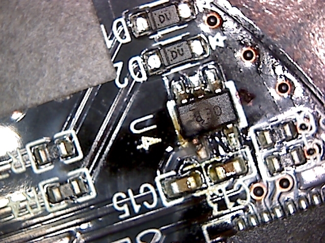
Each LED is set to draw about 8-10mA(led Vf is 2.4V max), and the processor should be drawing no more than 10mA and is asleep most of the time. in most cases I would think the current limit would kick in on this part before there was any kind of thermal issue. There is some package bulge and char.

Looking for some help with failure analysis. any help is appreciated.

  • Hi Matt,

    Would you be able to send us some scope shots of the input and output voltage when the part is failing? Also, is the part failing during startup or is it failing during normal operation of the part?

    Best Regards,
    Mark
  • Mark,

    I do not have any scope shots during failure, this is so far the only one that has failed out of a pilot run of about 75 pieces of this battery circuit. It failed in operation a few days after it was put into a field trial. I can see about putting some wires on another piece and grabbing some startup captures if you think that would help diagnose a potential issue.

    -Matt
  • Hi Matt,

    If you could send us some startup captures that would be helpful. Is the only load on the LDO the 4 diodes and the microcontroller? What is the maximum ambient temperature of the device? If the ambient temperature is too high you may be operating in thermal shutdown.

    Best Regards,
    Mark
  • Mark,

    Correct the only load would be the micro and diodes. 

    The battery goes into a wireless wearable device so operating ambient should be relatively low, I would say max 40-50C the lion cell would fail/vent in operation above 55C and dictates the upper limit of what the unit can handle.

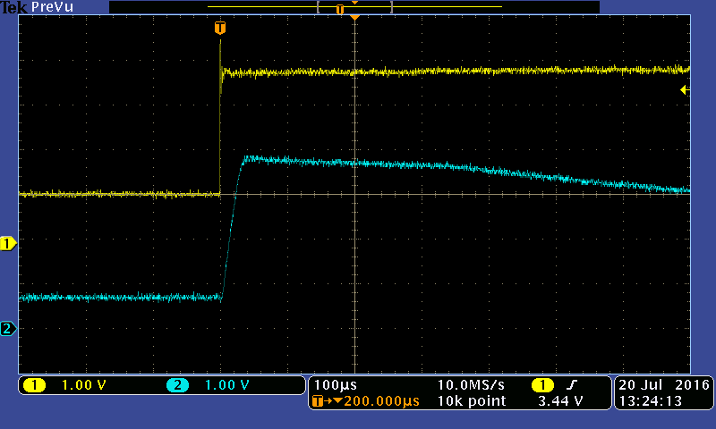
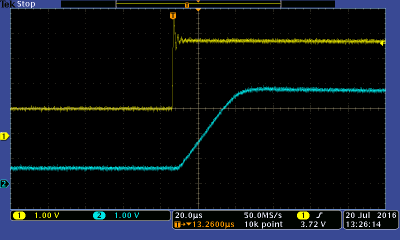
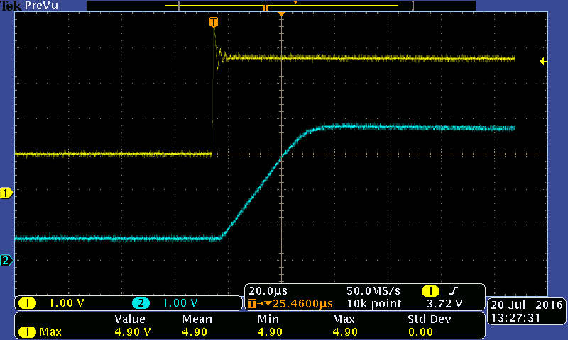
    Below are some captures of the most typical turn on even which is the battery recovering from a safety circuit event. I shorted the battery to enact the safety circuit then applied a 4V wakeup charge and triggered on the input (yellow trace 1). The ldo output is the blue (trace2).

    there are a couple different timebase captures. I think the input ringing is an artifact of the powersupply I was using but I am going to check that, in any case it was within the limits of the ldo input.

  • Hi Matt,

    I noticed a few things when looking at your scope shots.

    1) The regulator is a 2.85V and is consistently going up beyond 3.5V. In the first scope shot the output does eventually regulate down to 2.85V, but takes a long time. In the other scope shots the output of the regulator remains at approximately 3.8V for the duration of the waveform. Is there anything else on the rail that can be pulling the LDO output up? When you have the power supply at 1V the output of the LDO is at .7V, if you look at the startup curve it looks like when the input is at 1V the output should be 0V.

    2) The input supply as you mentioned is overshooting, in one of the waveforms it appears to go above 5V. It may be possible that the input supply is being brought over abs max during system startup.

    Hope this helps.

    Best Regards,

    Mark

  • Mark,

    attached is the entirety of the schematic. is there any reason the part is not regulating correctly? Its a relatively simple/small design. in my testing (scope shots) there is noting attached to J1 molex connector, this is the attachment point to a additional circuit board with LED and switch.

    Short of the part not operating correctly I cant see another reason for this overshoot on the LDO output to occur. 

    Would it be worthwhile to send a sample and or the failed part to TI to evaluate?

    Thanks!

    -Matt

  • Matt,

    Did you ever find a solution to this?  I came across it and was interested in what might be causing this as well.  Do you have any external circuitry on the HDQ line when running the tests?  

    My first thought is is there any way the battery was reversed when it was originally hooked up?  This could cause the LDO to be damaged prior to correctly hooking it up and, since there doesn't appear to be an protection for reverse voltage (and the LDO itself has an absolute min of -0.3V) , that could be a possibility.  

    I would also consider that you're pulling too much current when in full operation on the LEDs (I'm assuming you have 4 of them on your molex connector) and the micro itself but, like you said, I would assume the chip would just limit the output current without damaging the chip).  

    There could also be a short on the board you have (I've seen internal shorts on circuit boards, even from companies that claim to do 100% testing like Advanced Circuits).  It might be worth it to test the resistance between some of those pins and other places on the board and compare them to working boards (this may require you to remove chips though, which isn't fun).  

    Lastly, we have purchased some DCP022415DU chips from TI in the past and had an entire batch that was bad and caused a lot of damage to some of our boards.  I only mention this because it was a TI part and we were able to identify the damaged ones very easily by a bubble on the chip similar to yours.  I would double check everything else first but, if you have a number of boards that all behaved correctly and this is one board that didn't, it wouldn't be impossible that it could be a bad chip.  

    Let me know if you find out the root cause of this!  Thanks!