This thread has been locked.

If you have a related question, please click the "Ask a related question" button in the top right corner. The newly created question will be automatically linked to this question.

TPS7A19: TPS7A1901DRBT Output Does not regulate after power cycling

Part Number: TPS7A19

We are using this regulator to step down our input voltage(9-16VDC).  Output current is less than 100mA the majority of the time.  The current kicks up to 300mA with communications operating.

The problem we are running into is that the regulator loses regulation.  The output is typically at OR around 3V when damaged. 

The only thing we can find is that we sometimes have a voltage dip from 13.5VDC to 5VDC for 100uS after the initial power up.

We have not able to measure an overvoltage to the input of the regulator.  The FB pins appears to be undamaged because the clamping diodes still measure from ground to the pin the same as a good chip.

If we replace the regulator, this is the only failed component in the assembly.

Please let me know what your thoughts are as some tests we can perform or other items to look for.


Thank you

Matt

tps7a19-RegCircuit.pdf

  • Matt,

    Would you be able to give us more information about your application? What is the regulated output voltage? If the input supply is dropping below the regulated output voltage the part can experience reverse current, which has the potential to cause damage to the LDO.

    Do you have an scope shots of the LDO failing? Also do you have any way that you are able to look at the input current to the LDO during startup/shutdown?

    Regards,
    Mark
  • The output voltage is 6.8VDC.
    Yes the input to the regulator does drop below the 6.8V, momentarily(100uS as indicated above) when first powered up. There is a high inrush and current draw on power up

    The problem is sporadic and we have not been able to capture it. We power cycle units 100's of times and 1 unit may fail from this phenomenon.

    There is a p-channel fet in this chip. The body diode appears to be undamaged on the failed units(measures the same as a good unit with a diode checker from input to output).
  • Hi Matt,

    When you are power cycling are you letting the input and output go all the way to 0V? If you have a large reverse current there is a potential for latch-up to occur and if the part is powered back up before the latch-up is removed it can cause some problems.

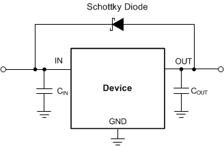
    You may want to try to put a fixed load resistor on the output or place a schottky diode from in to out as shown below.

    Regards,

    Mark

  • Is the Schottky diode needed, if the p channel fet used in the device has its' body diode connected from out to in? In the same orientation as shown above.
  • Hi Matt,

    That diode that is there is not a protective diode it is a parasitic diode. The schottky diode will have a lower forward voltage than the body diode, which it will keep the reverse current going through the part causing damage.

    Regards,
    Mark