This thread has been locked.

If you have a related question, please click the "Ask a related question" button in the top right corner. The newly created question will be automatically linked to this question.

TPS7A4001: FB and Vout pin failure when battery is attached

Part Number: TPS7A4001

Hi team,

It is found that TPS7A4001 is easy to be damaged when the battery is attached to the circuit.

Now a 80V battery is used for the input of TOS7A4001, the output is 40V, the typical load is about 2mA in the application.

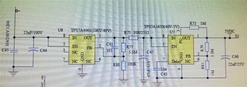
Below is the schematic.

The damaged has been seen for pin FB and Pin OUT (both or one of them), the impedance is usually about 350~500Ohm for between OUT and GND, FB and GND, OUT and FB.

I have checked the waveforms on VIN, OUT, FB, EN pin, no large peak(almost no overshoot)voltage have been seen, all are in the spec of datasheet. (during start and steady state)

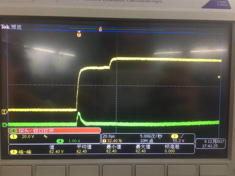
After that, I also checked the output current during start. (The current of R75, other wires have to be cut, not easy to test, still no enough time) Large current could be observed, see below.( Yellow: input voltage; blue: output current)

It seems soft start doesn't make some impacts. Why? Is it related to high dv/dt?

Thanks.

  • In addition, no short has been observed from VIN to OUT.
  • Hi Robin,

    Thanks for posting the scope shot with your post. Would you be able to provide more scope shots showing Vin, Vout, Vfb, and Iout. This will be able to help us see what is going on. If you could aslo try shorting R75 this may help you as well. You are adding 10 ohms of ESR to the output capacitor, which may cause some stability problems. If you need that resistor I would recommend placing it either before the LDO, or after the output capacitor.

    Best Regards,
    Mark
  • Hi Robin,

    Could you also show us a picture of the input current? It looks like it may be going very high for ~40us, which may cause some problems.

    Regards,
    Mark
  • Hi Robin,

    I agree with Mark that you should at least adding another capacitor before your R75 resistor; with the R75, your current schematic does not have the required capacitance at the output of your TPS7A4001.

    Another potential issue seems to be related to the capacitor C41. When you have a sharp voltage transition at startup, your feedback pin of the TPS7A4001 may exceed the maximum voltage allowed which is only 2V due to the the existence of the 10nF C41. When this happens, your FB pin could be damaged first. Once your feedback pin gets damaged, you could see a very high gain on the output of the TPS7A4001, which may damage the output pin as well. Like Mark suggested, the first 40uS, the battery's voltage is only 65V. It could be caused due to heavy load on the battery which may be caused with damaged FB pin. In order to confirm if this is the case, please monitor your FB pin of TPS7A4001 during your startup to see if the voltage indeed exceeds 2V.

    Regards,
    Jason Song

  • Thanks all for the reply.

    Jason, 

    For the second point about C41, we noticed it before and removed it. The failure still is there. About 400 pcs boards were manufacture and one failure was found. 

    It is understood that the schematic is not good, and it may have instability issue. But it is hard to convince customer that this instability could cause the damage.  Because and the chip damage is burn with fire, customer concerns the other good board could have the same problem in the future some day, and they have to stop the manufacturing and pend all the end products shipment. if they remove the R75 and still can catch failure after manufacturing thousands boards, the thousands boards means a very high loss to them. One board costs 100 USD. 

    1) From the current waveform, you can see a big inrush output inrush current. if the SS function works, it should not happen. So, our question is that, could the high dv/dt cause the SS failure?

    2) The failed part shows low resistance (~300Ohm) from FB pin to GND pin. If the FET damage is caused by the inrush current, why FB circuit is damaged?

    3) after remove C41, we monitored the FB voltage and didn't find the high voltage. So the FB should be damage by direct high voltage on it.

  • Hi Zhengxin, 

    Thanks for providing us more details. If problem still exists after C41 being removed, it's likely that FB pin gets damaged during startup due to the overshot of the vout. As we have stated early, the schematic does not have the output capacitance required for the operation of the LDO. Without the output capacitor, you will most likely see a large overshot on the vout of your first stage LDO after you apply the 80V battery. 

    In order for us to identify the issue, will you provide a screenshot that includes Vin, Vfb and Voutput for the startup behaviors on the device? The screenshot will help us identify the root cause. If you could also include in-rush that you already have, that would be better. Usually in-rush won't necessarily damage the pin, the pin is more likely being damaged by voltage. 

    Regards, 
    Jason Song

  • Hi Zhengxin,

    As Jason said we will need more information to help you solve this problem. It is possible that you may be causing problems on the input of the LDO with the fast transient. Can you try slowing down the input voltage waveform and see if that resolves your problem? The other thing you may want to try is seeing if moving the 10ohm resistor in front of the LDO resolves the problem as it will help limit the current rushing through the LDO.

    Regards,
    Mark