This thread has been locked.

If you have a related question, please click the "Ask a related question" button in the top right corner. The newly created question will be automatically linked to this question.

TPS737: 【Repost】Could you tell me about TPS73701's suspicious behavior?

Part Number: TPS737
Other Parts Discussed in Thread: TPS73801, TPS74401, REG104, LM4132

I'm sorry, I have posted below.

e2e.ti.com/.../2437515

Can you tell me about the last post?

<Last post>

Next, on the point that I asked 「Is not it a mistake of" very fast "?」, The waveform in Figure 23 of the data sheet is 2 msec / div for 50 msec / div.

Comparing the behaviors at startup, I think that the customer's waveform and the red frame below are the same,

so when comparing the time axis of this point, I felt that the customer waveform started " very fast ".

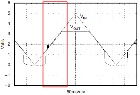
Is my opinion wrong?

  • Hi Sekiguchi-san,

    Generally we consider 1 V/usec or 2 V/usec ramp rate as "fast". Vin from this datasheet plot is rising 5 V over 170 msec = 30 uV/usec. This would be considered a slow ramp.

    During the last 2/3 of startup where Vout approximately equals Vin, the LDO is in dropout. As John mentioned, the error-amplifier is railed and the pass FET is fully-on. Exiting dropout into regulated output voltage at the end of startup can lead to output voltage overshoot. Some LDO designs will have no overshoot exiting dropout and others will show more overshoot.

    Your customer plot shows the 3 V output overshoot up to 3.21 V at the end of startup. This is 7% above the 3 V output. If this amount of overshoot is unacceptable, you may need to choose a different LDO.
  • Thank you very muych for your answer, Eric-san.

    Ⅰ: So including past interactions, are the measures correct as follows?
    ① Power ON the IN pin voltage rised, and then turn on EN pin.
    ② Replace with another product.

    Ⅱ: What is the reason for this overshoot?
    (I want to know for customer explanationing, it's OK by guessing.)
    ・Does it depend on the response speed of the internal circuit?
    ・Will it depend on the minimum operating voltage of the internal circuit?
    ・Other reasons?

    Best regards,
    Pokkun(Masumi Sekiguchi)
  • Hi Sekiguchi-san,

    You are welcome.

    1) Yes, to avoid dropout during startup: ramp IN pin, then ramp EN pin later. Dropout is 0.5 V max on TPS737.
    2) Yes, replace if ramping EN pin later is not an option.

    3) Reason: It depends on the response of the error-amplifier. If the error-amplifier has a small bandwidth it will take longer to respond and the overshoot will be larger before the error-amplifier corrects the output voltage.
    It does not depend on the minimum operating voltage or other reasons.
  • Hi Eric-san,
    Thank you for high-quality answer!

    I could understand the countermeasure and the reason, so I'll reply with confidence to the customer.

    Best regards,
    Masumi Sekiguchi
  • Sorry, I would contact you one more.

    When I was answering for customer with the contents received, I got the following question.
    I will also write my own idea so can you give me advice?
    ※Also, the thing is NG that turned ON at the EN pin after VIN, because EN signal is taken from another system board.

    <Customer's Question>
    Customer is using TPS737 at the output setting 3.0V, and this output drives an IC with an absolute maximum rating of 3.4V.
    Q: Is it possible to guarantee that the output does not become 3.4 V or higher regardless of the input rise time?
    Q: If you can not guarantee that it will not go above 3.4 V, please tell me the range of rise time that can be used at 3.4 V or less.


    <my mind>
    I don't want to discuss about "guarantee" as much as possible with customer.
    So, I will try to answer this question without issuing a word of "guarantee".


    So question.
    Question1:I'll propose the following two devices as substitutes.
    Can you assert that "If this device is choiced, will not over shoot more than 3.0V!"
    · TPS73801
    · TPS76701Q

    Question2:In addition, can you tell me the numerical value for the range of rise time that does not exceed 3.4 V if you can compensate customers questions?

    I will try to answer this reply as "Theoretical Value" to the customer.

    Could you help me?

    Best regards.

  • Hi Sekiguchi-san,

    The Vin ramp rate on the customer's board is in a middle region between fast ramp rate and slow ramp rate. In this middle region, some LDOs like the TPS737 will overshoot on startup. It is difficult to bound the amount of overshoot.

    1) What is the customer's max output current requirement?

    2) Do you require the SOT-223 (6-pin) package?

    TI has a demonstration module for SOT-223 LDOs: www.ti.com/.../dem-sot223ldo
    You could use this demonstration module with TPS73801 to verify if startup overshoot occurs.

    Some LDOs will not overshoot on startup. I have significant experience using the TPS74401 in power designs, and this part does not overshoot on startup. An EVM is available for the TPS74401, but this part does not come in SOT-223 (6-pin).
  • Thank you very much, Eric-san.

    The Vin ramp rate on the customer's board is in a middle region between fast ramp rate and slow ramp rate.

    In this middle region, some LDOs like the TPS737 will overshoot on startup.

    It is difficult to bound the amount of overshoot.

    1) What is the customer's max output current requirement?

    ⇒The customer's max output current requirement is "1.0 A".

    2) Do you require the SOT-223 (6-pin) package?

    ⇒I want to promote SOT-223(6-pin) as pin compatible as possible.

     But the customer said be able to change the PCB layout pattern.

     So we can promote another package if it's the package with feet, too.

    ※There is always a constraint that this customer must be adoption only the package with feet.

    <Customer Specification>
    VIN:5.0V

    VOUT:3.0V

    IOUT:1.0A

    ※must only the package with feet.

     Please let me know the device if that meets this adoption criteria and there is a device that can make a decision not to overshoot this time.

     I'll introduce it as an alternative item.

    Best regards,

    Pokkun (Masumi Sekiguchi)

  • Hi Sekiguchi-san,

    Another TI LDO to consider is the REG104.

    I will order the SOT-223 (6-pin) demo board, REG104-Adj, TPS73801 and test startup to check for overshoot.

    What are the customer spec requirements?
    Operating temperature range
    Output voltage tolerance
    Iq and Ignd
  • Hi, Eric-san.

    Thank you very much for your reply.

    > What are the customer spec requirements?

    > Operating temperature range
    ⇒ It is not designated, now.
    > Output voltage tolerance
    ⇒ The overshoot does not become 3.4 V or more.
    ※ Because the TPS737's Output's next device absolute max rating is 3.4V.
    > Iq and Ignd
    ⇒ It is not designated, now.


    I had a meeting with the customer on this subject.

    Replacing the TPS73701 device requires a lot of resources, so I want to avoid it.
    Therefore, after confirming the following, I would like to explore the possibility of continued use.

    Could you help me?

    ① I want to know the WORST value of the overshoot that occurred this time.
    ② Please also tell me the reason for overshoot occurrence once again.
    ※I have checked the customer's situation, no overshoot occurred when the power was steeply turned on using the switch.
    ※Therefore, it is difficult to think that responsiveness of the internal circuit is caused by the fact that overshoot does not occur at the time of steep startup.
    ※Therefore, it is unlikely that will have occurs from response of the internal circuit, since overshoot does not occur at the time of steep startup.
    ③ Does not overshoot Tell me the slew rate of power supply startup.
    * Datasheet p11 I think that it can be determined if product evaluation is conducted at multiple slew rates based on the results in Figure 23.

    Best regards.
  • Hi Sekiguchi-san,

    I understand the reasons for keeping the TPS73701 in the customer's design. I ordered the TPS73701 and will evaluate startup response to answer your questions. What is the customer using to provide the 5 V in their application?
  • HI, Eric-san.
    Thank you very much!

    I checked supply power information on customer's application.
    · Power supply equipment used for this customer evaluation
    · Power supply behavior supplied when assembling applications

    I think that there will be immediate contact from customers, so I will contact you again.

    Best regards.
  • HI, Eric-san.
    I heard from the customer.

    The customer confirmed them together with the following two devices, and it is the same phenomenon.
    · PAN 35-5A
    · P4K-80
    The sent waveform was measured with PAN 35-5A.

    The power startup time assumed by the application is in the range of 20 to 200 [msec].
  • How long will it take me to receive this answer?
  • Hi Sekiguchi-san,

    The TPS73701 parts and demo board will arrive tomorrow (28-Feb). I should be able to test the same day and send the results.
  • Thank you for contacting me.

    Then please proceed with the evaluation as soon as the sample arrives.

  • Would you get the following anythings of by the measurement ?
    ・Regarding the reproducibility of the phenomenon of Overshoot
    ・When reproducing, the reason and mechanism of Overshoot.
     Also, the overshoot WORST value.
    ・Restrictions on the continued use of TPS73701.
    (Example:Shoot will not happen by setting the slew rate at power-on start to less than *****.)

    Best regards.

  • Hi Sekiguchi-san,

    The parts arrived at the end of the day. I'll test in the morning and send you the results.
  • Thank you for your responce.
    I understood the situation.
    Thank you, please you are continue.
  • How was the evaluation result?
  • Hi Sekiguchi-san,

    Sorry for the delay. I had 2 validation projects last week. I have the board built up and a test sequence ready to test on Monday, 5-March.
  • Hi, Eric-san.

    Thank you for contacting me.
    I'm waiting for the results of the evaluation.

    Best regards,
    Pokkun(Masumi Sekiguchi)
  • Hi Sekiguchi-san,

    I ran 401 startups with different Vin and En ramp rates and min to max load current on the TPS73701. I'm attaching two scope shots with maximum overshoot in the range: 0.6 to 0.7 V (max Vout = 3.7 V). All other overshoots were in the range of 0 V to 0.4 V. We can bound the overshoot at 3.7 V max on the 3.0 V output.

  • Hi Sekiguchi-san,

    I wanted to address your other questions:

    The internally controlled typical start up time is 600 usec for this LDO. If the Vin ramp is < 600 usec, overshoot will not occur.

    Overshoot only occurs when the Vin ramp rate is slower than the TPS73701 internal softstart. Vin ramp rates greater than 600 usec can result in overshoot. Since the customer's application has Vin ramp up time of 20 - 200 msec, there is possibility of overshoot on startup.

    Overshoot ranges from 0 V to 0.7 V with Vin ramping to 5 V and output set to 3 V. Most of the overshoot is in the range of 0.05 V to 0.5 V. Only two tests showed overshoot > 0.5 V.

    WORST value of overshoot is 0.7 V (Vout = 3.7 V) from scope shot in my previous message.

    Mechanism:
    When Vin ramp rate is slower than the LDO internal softstart startup rate, the LDO Vout = Vin during a portion of the startup. During this time the LDO is in Dropout mode. In Dropout, the pass FET is fully on. Once the Vout = 3 V, the error-amp has to pull charge out of the pass FET to bring it back into linear region to remain at 3.0 V. This takes some time due to the bandwidth and drive capability of the error-amp and buffer that drive the pass FET. In the first of my scope shots, the response time is measured from the Vout crossing 3 V until the peak of the overshoot = 1.4 msec. This equates to a bandwidth < 1 kHz, which is common for many LDOs. At the peak of the overshoot, the error-amp and buffer are able to pull the pass FET back into linear region and the output ramps back down to the desired 3.0 V.
  • Thank you for sending data.
    ①:Can I send datas under other condition?
    ※Because we must determine whether it will fit overshoot below 0.4V and respond to customers.


    Also, considering the customer's application, it is a problem if it exceeds 0.4 V even once.
    ②:I think that it is possible to suppress to overshoot of less than 0.4V if the slew rate is 20~200 msec which is the customer's condition,

    is my idea correct?

    Because:

    it is 1.4 msec from "when VOUT exceeds 3 V" to "overshoot peak", even though it is estimated at 2 msec,

    it thought that if shoot is started up with a slew rate of 0.2 V / msec more, a shoot of 0.4 V or more will not occur to be.

    If the mail is easier to present the data, please contact the address below.

    masumi_sekiguchi@marubun.co.jp

  • Hi Sekuguchi-san,

    It is fine to continue through this forum to address this issue.

    1.4 msec is the measured amount of response time in my scope shots. See annotated plot:

  • Hi Sekiguchi-san,

    I reviewed your original post with the customer's scope shot and 2 msec response time.

    I agree with your math that a slower ramp of Vin at 20 msec or longer will reduce the amount of overshoot on startup to 0.4 V or less. I reviewed my measurement data for scope shots with 20 msec or longer Vin ramp time. I'm including 3 scope shots with 20 msec Vin ramp time and overshoot to 0.4 V. For margin, the input ramp could be increased to greater than 20 msec.

  • Hi, Eric-san.
    Thank you very much for great response!

    Well, I will talk about the introduction of alternative items for customer, please tell me in the end.

    Could you be declared that replacing the following below devices introduced from can keep the overshoot under 0.4V?
    ・TPS73801
    ・REG104
    ・TPS74401

    Best regards.
  • Hi Sekiguchi-san,

    I have the TPS73801 and REG104 in my office. I will have to order the TPS74401 EVM.

    TPS73801 and REG104 are in the SOT-223 6-pin package, with same pinout as TPS73701. I should have time to evaluate both at 20 msec Vin ramp by the end of the week.

    TPS74401 is not available in SOT-223 6-pin. Do you still want that part evaluated?
  • Hi, Eric-san.

    Thank you for your response.
    I'm sorry for late contact.

    Could you evaluate the following devices ?
    ・TPS 73801
    ・REG 104

    Also, please evaluate TPS74401 if the degree of overshoot is bad after confirming this result.

    Best regards,
    Masumi Sekiguchi
  • Hi Sekiguchi-san,

    TPS73801 has good startup performance with no overshoot. I tested at 0 A, 3 mA, 750 mA load and the waveform looks the same.

    REG104 has more overshoot than TPS73701 and I do not recommend for your application:

  • Thank you very much for the best support !!
    It was very helpful.

    I have responded to customers with this answer.

    Best regards,
    Masumi Sekiguchi
  • Hi Pokkun,

    does it make any change if you omit C1503 or increase it?

    I had a similar problem with the voltage reference LM4132. The 3.3V version showed an overshot of 4.0V:

    e2e.ti.com/.../653035

    The only solution was to change the chip! I guess you experience something similar. You should really take into consideration to take another voltage regulator.

    Kai

  • Thank you for your response.
    Sorry, my contact have lateed.

    The customer was satisfied with the answer so far.
    However, please let me ask another question.

    <Question>
    Can you tell me the MIN / MAX of the TPS737 startup time specification?
    (I understand the TYP value is 600 μs.)

    <Reason for question>
    Most models that customers have used TPS 737 in the past often have an average startup time of 1 msec or more.
    In order to judge which model you need to change, I'd like you to have this specification in detail.
    ※I think 3σ data is helpful.
  • Hi Sekiguchi-san,

    I'll continue looking today for startup time data on the TPS737. I have not found it yet.
  • Hi Sekiguchi-san,

    I looked through some archived data and found a few typical startup measurements.
    Startup times were 1 msec and 1.2 msec across a few voltage options.

    Unfortunately this is an older part (Released 2006), so I do not have access to more data from the designer.

    A conservative estimate would be startup time max = 2 msec and use that to evaluate the customer's designs.