This thread has been locked.

If you have a related question, please click the "Ask a related question" button in the top right corner. The newly created question will be automatically linked to this question.

TPS7A7200: Data sheet recommendation.

Part Number: TPS7A7200

A customer is attempting to determine the appropriate input capacitance for the TPS7A7200RGWR. He linked the datasheet below. In section 8.2.2.3 the best guideline was to use a capacitor of up to 1uF. However, later in the datasheet in section 9 it recommends to use a 10uF input capacitor.

He assumes the larger capacitance is attempting to be avoided because of the resonant point with the ESL of the trace. A smaller capacitor would cause the resonant point to be pushed out further.

1. In general, can a 10uF capacitor be used with some level of confidence with optimized trace routing?
2. Is there perhaps a tool to use to determine the input impedance for the converter so the input stage could be designed to have a smaller impedance?
http://www.ti.com/lit/ds/symlink/tps7a7200.pdf

Regards,

Naser

  • Hi Naser,

    Usually PCB manufacture will provide inductance calculator for trace inductance estimate using parameter such as wire length, thickness and width. With 5nH parasitic inductance and 10uF input cap, the AC transfer function has a peak of 20dB gain at 700KHz. If noise and PSRR is very critical for your application. You should consider make the LC resonant frequency outside the bandwidth of the control loop as datasheet suggested.

    In general, with proper trace routing, the trace inductance can be limited to a few nH. Again if noise/PSRR is critical for your application, make sure to get the inductance information from PCB manufacture and run an estimation.

    Regards,
    Jason Song
  • Hi Jason:  Thank you for the response. I  shared with customer. He  does have a tool he can use to estimate the trace inductance.  See his comesnt below

    From what you are saying, I  could try to create a trace route that has a LC resonance beyond the bandwidth of the converter. If I was to head this route, do you know the bandwidth of the converter? I didn’t seem to find it in the datasheet.

     Ideally I would be able to do an input – output impedance analysis (Middlebrook’s criteria) on the converter to verify stability. Do you have an AC simulation model that I could use to verify this with?

    Regards,

    Naser

  • Hi Naser,

    Are you asking for Pspice model for TPS7A7200? You can find the model here:
    www.ti.com/.../toolssoftware
    You should be able to use TI's Tina simulator for simulation.

    What is the previous stage that drives the LDO? To be more specific, what would be the input impedance over frequency from the supply that powers the LDO? This will have a impact on the stability of the LDO as well. 

    Regards,
    Jason Song

  • Hi Jason: Per customer

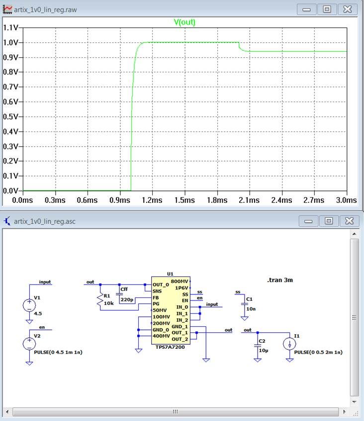
    I attempted to use the PSpice model but I get some erroneous results with it. When I introduce a 500mA load I see a 0.5V drop from regulation (Vin=4.5V). So I’m not sure if I can trust the model or not. Do you know why this would be? I captured a screenshot of what I am seeing at the bottom of this email.

     The stage right before the LDO will be a 1.8V switching converter (4A).

     Do you know what the bandwidth of the TPS7A7200 is?

    Regards,

    Naser 

  • Hi Naser,

    I agree, the simulation seems to have a problem with PSPICE model. For the loop response, from the datasheet, there is no clear chart that we can use to estimate. The common bandwidth for LDO is around 1-2MHz; the datasheet has discussion on bandwidth, but there is no value mentioned. If you really need to know the bandwidth, we can run an estimation using load transient. Can you share me with the switching converter part number? I can take a look at the output impedance of the converter as well.

    Regards,
    Jason Song
  • Hi Naser,

    In order to ease the concerns about stabilities problem with the added impedance at the input, we can estimate the bandwidth of the LDO to be between 1MHz to 2Mzh. As long as you have the LC frequency (1/2pi √lc) within 200KHz or above 2-3Mhz for this device, we should be good. We just cannot have the LC frequency too close to the bandwidth of the LDO because the worst phase margin is around the bandwidth. If you can estimate the inductance from the layout, we can use the value to pick the input cap; we can either do a small cap up to 1uF with careful layout or we can do a tantalum cap which will limit the LC frequency inside the loop but still far from the bandwidth.

    Regards,
    Jason Song