This thread has been locked.

If you have a related question, please click the "Ask a related question" button in the top right corner. The newly created question will be automatically linked to this question.

TPS40210 cannot boost up to 100V output

Other Parts Discussed in Thread: TPS40210, SWITCHERPRO, TINA-TI

Hi,

I would like to use TPS40210 to generate a +100V/0.5A output.

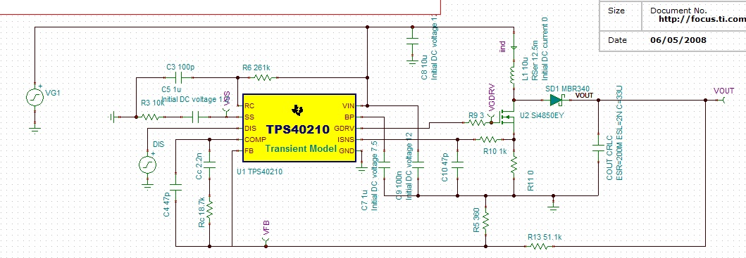
I had downloaded the TINA reference design from TPS40210 webpage, and modified the following items to generate +100V output

  • remove the load on output
  • set over-current protection resistor(R11) to 0 Ohm, ignore this function for now
  • output voltage divider R5 set to 360 Ohm, so I should get 100V on output

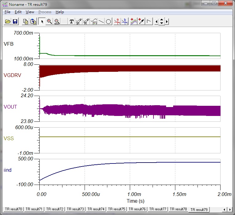
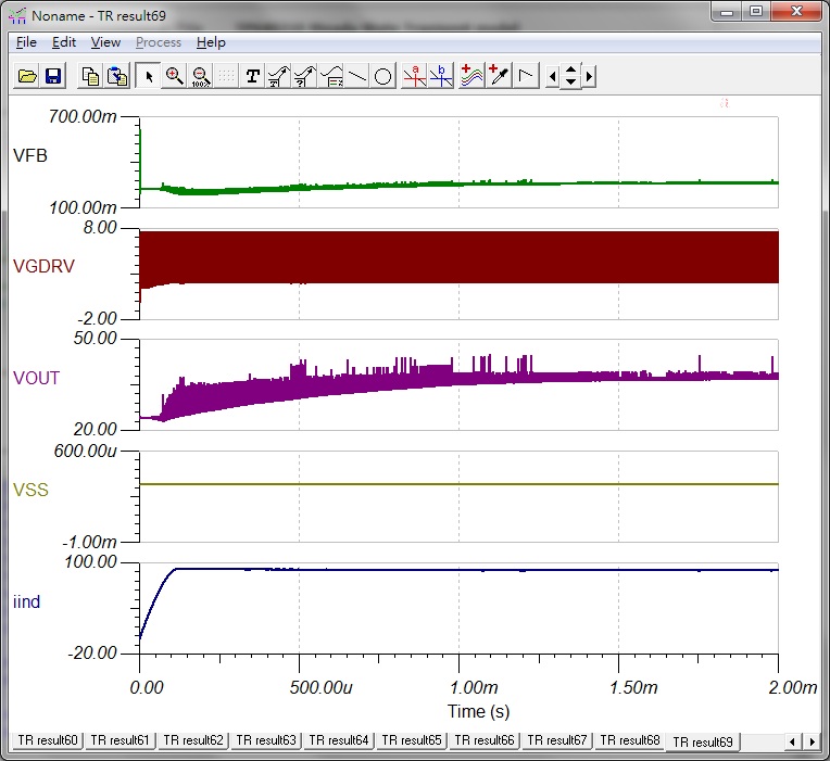
However, output voltage can only be boosted up to about 40V, as the following figure. I had tried to adjust switching frequency and control loop filter(COMP pin), but the problem still the same.

I also attached the TINA simulation file as below, can someone give me a hand ?

2845.[Nate]TPS40210_TRANS_Steady.TSC

Thanks a lot.

  • Hi Shang-wei,

    In reality the TPS40210 should work in the 100V output at 0.5A application. I'll see if i can't help you figure out why the simulation won't run properly.

    Regards,
    Anthony

  • Hi Shang-wei,

    There are a couple things going on here making this not work. Properly rated components the TINA Model simulates the breakdown voltage of the schottky diode. Once you're above the breakdown voltage it will conduct in the opposite direction. The same goes for the MOSFET. I recommending selecting all components you expect to use in this design first. SwitcherPro can probably give you a good starting point.

    Also notice there are two different transient models for the TPS40210. One for startup and steady state. When using the steady state model with such a high output voltage I recommend also putting an initial condition on the output capacitor at the desired output regulation voltage. This will help avoid hitting current limit because the model will instantly attempt to charge the output capacitors at maximum duty cycle. If you are not charging up the output with the slow start there is a good chance you will hit current limit.

    Regards,
    Anthony

  • Hi Anthony,

    Thanks for the reply.

    I replaced MOSFET and Diode to higher rating parts,

    • MOSFET : Vishay SiR878DP, VDS = 100V / Continuous Drain Current = 40A@25 degree
    • Diodes : On-semi MBRS1100T3, brackdown = 100V / junction potential = 336mV
    But I still cannot get 100V output from TPS40210, only 24V output with fairly large noise.
    I am new to TINA and do not know how to set the initial voltage on the output capacitor(COUT).
    Below is the modified TSC file, could you help again ?
    Thanks a lot.
  • Hi Sheng-wei,

    I think we are running into the gate drive current limitation of the controller. Please find attached a simulation which can regulate to 100V with no load. I chose the design by using a SwitcherPro. 4643.TPS40210 100V.TSC

    You can set the output voltage by right clicking on the output capacitors, hit "Enter Macro" and change the IC parameter to your desired output voltage. I have it set to 99.5V in the attached.

    As the load is applied the output voltage begins dipping because it cannot provide enough power to the output. This can be solved by adding external BJTs to amplify the current of the gate drive signal. This is shown circled in red in the schematic below from a similar design.

    Increasing the input voltage will help a lot in this design. Do you need your design to operate with a 12V input?

    Regards,
    Anthony

  • Sheng-wei,

    I managed to get this working properly. One of the FETs in the TINA sim I sent you previously was wrong causing incorrect operation. This will work without the two additional BJTs and with only 1 FET. New sim is attached.

    8750.TPS40210 100V.TSC

    Regards,
    Anthony

  • Hi Sheng, what Tina version did you used?

    I'm trying to run your simulation with tina-Ti 9 but it throws a convergence error, I didn't change anything apart of the unconnected components.

    Thanks