• Join
  • Sign In with my.TI Login
Texas Instruments
  • Products
  • Applications
  • Tools & Software
  • Support & Community
  • Sample & Buy
  • About TI
Sample & Purchase Cart Sample & Purchase Cart
  • Search
  • Advanced
TI E2E™ Community
  • Support Forums
  • Blogs
  • Groups
  • Videos
  • 简体中文
  • More ...
TI Home » TI E2E Community » Support Forums » Power Management » Non-Isolated DC/DC » Non-Isolated DC/DC Forum » TPS54325 PCB Layout
Share
Non-Isolated DC/DC
  • Forum
  • E2E Wiki
Options
  • Subscribe via RSS

TPS54325 PCB Layout

TPS54325 PCB Layout

This question is not answered
George Ioakimedes
Posted by George Ioakimedes
on Dec 31 2012 13:42 PM
Intellectual910 points

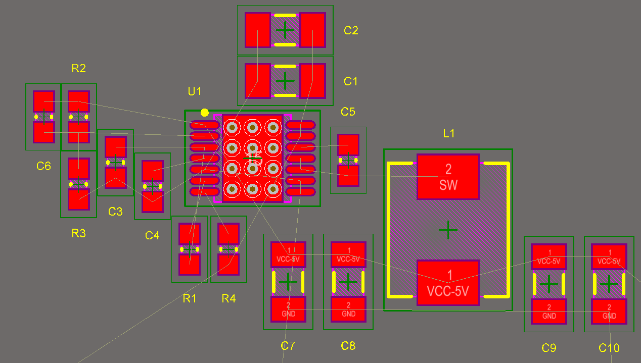
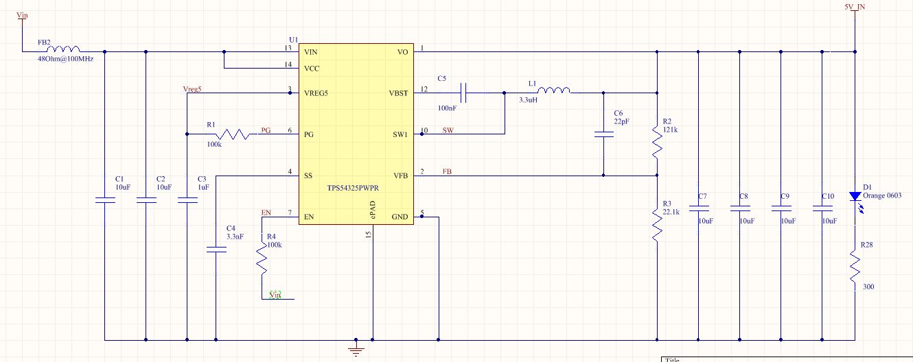
I was getting ready to do a board layout with the TPS54325 and thought it wouldn't hurt to get some feedback on my part placement before I started the routing. I'll have a 12V input and actually 2 of these circuits in parallel, one to generate 5V and the other to generate 3.3V.

I like these part positions as they allow for the most direct routing and I believe also cover all the layout guidelines. The feedback resistors are a little farther away from the switcher than I'd like but having them there means a direct shot into the part for almost all signals.

Anyway, hoping for some feedback (pun intended!) so I can try and finish the board layout before the New Year.

Thanks & Have a Great 2013!!!

Report Abuse
  • Reply
You have posted to a forum that requires a moderator to approve posts before they are publicly available.
All Replies
  • JohnTucker
    Posted by JohnTucker
    on Dec 31 2012 13:56 PM
    Guru50125 points

    In general that looks ok.  Make sure to get c1 and c2 as close as possible to the IC.  The SW node copper area should be as small as practical without making it long and thin (short and wide is better).  So you may want to look at the U1, C5, L1 relationship.  I would probably be inclined to move L1 closer and move C5 up.  To minimize the output circulating path, you may want to rotate L1 90 degrees so the output side is facing down.  you can then move the output caps to the left of the inductor rather than the right with the ground side facing up.

    John Tucker

    Consumer DC/DC Applications

    Report Abuse
    • Reply
    You have posted to a forum that requires a moderator to approve posts before they are publicly available.
  • George Ioakimedes
    Posted by George Ioakimedes
    on Dec 31 2012 15:54 PM
    Intellectual910 points

    Hi John:

    OK, if I move C5 above L1 (after rotating it 90 degrees) I can then move L1 very close to U1. By doing that I wouldn't have enough room to fit all 4 output caps to the left of L1. Would it be better to move R1 and R4 so all 4 output caps fit basically below U1 or would it be alright to split the output caps and put 2 on either side of L1?

    Report Abuse
    • Reply
    You have posted to a forum that requires a moderator to approve posts before they are publicly available.
  • JohnTucker
    Posted by JohnTucker
    on Dec 31 2012 17:24 PM
    Guru50125 points

    You can array them in different ways, the main thing is to place them so the loop from SW to L1 to Cout and back to the IC ground has a small loop area.

    John Tucker

    Consumer DC/DC Applications

    Report Abuse
    • Reply
    You have posted to a forum that requires a moderator to approve posts before they are publicly available.
  • George Ioakimedes
    Posted by George Ioakimedes
    on Dec 31 2012 17:39 PM
    Intellectual910 points

    OK, gotcha. I didn't completely move C5 out of the way because I wanted to make sure that I had enough room to do a big copper area for Vin.

    .

    Report Abuse
    • Reply
    You have posted to a forum that requires a moderator to approve posts before they are publicly available.
  • George Ioakimedes
    Posted by George Ioakimedes
    on Jan 04 2013 13:58 PM
    Intellectual910 points

    Getting ready to do some copper pours and I thought it wouldn't hurt to have a 2nd pair of eyes take another look at the layout if you don't mind.

    Report Abuse
    • Reply
    You have posted to a forum that requires a moderator to approve posts before they are publicly available.
TI E2E™ Community
  • Support Forums
  • Blogs
  • Videos
  • Groups
  • Site Support & Feedback
  • Settings
TI E2E™ Community Groups
  • TI University Program
  • Make the Switch
  • Microcontroller Projects
  • Motor Drive & Control
Other Communities
  • Deyisupport
  • Designsomething.org
  • beagleboard.org
  • TI on Element 14
  • TI on TechXchangeSM
Other Technical & Support Resources
  • WEBENCH® Design Center
  • Product Information Centers
  • Technical Documents
  • TI Design Network
  • TI Technical Articles
  • TI Training

All content and materials on this site are provided "as is". TI and its respective suppliers and providers of content make no representations about the suitability of these materials for any purpose and disclaim all warranties and conditions with regard to these materials, including but not limited to all implied warranties and conditions of merchantability, fitness for a particular purpose, title and non-infringement of any third party intellectual property right. TI and its respective suppliers and providers of content make no representations about the suitability of these materials for any purpose and disclaim all warranties and conditions with respect to these materials. No license, either express or implied, by estoppel or otherwise, is granted by TI. Use of the information on this site may require a license from a third party, or a license from TI.

Content on this site may contain or be subject to specific guidelines or limitations on use. All postings and use of the content on this site are subject to the Terms of Use of the site; third parties using this content agree to abide by any limitations or guidelines and to comply with the Terms of Use of this site. TI, its suppliers and providers of content reserve the right to make corrections, deletions, modifications, enhancements, improvements and other changes to the content and materials, its products, programs and services at any time or to move or discontinue any content, products, programs, or services without notice.

Follow Us Texas Instruments on Facebook Texas Instruments on Twitter Texas Instruments on LinkedIn Texas Instruments on Google+
TI Worldwide | Contact Us | my.TI Login | Site Map | Corporate Citizenship | mobile m.ti.com (Mobile Version)

TI is a global semiconductor design and manufacturing company. Innovate with 100,000+ analog ICs and
embedded processors, along with software, tools and the industry’s largest sales/support staff.

© Copyright 1995-2013 Texas Instruments Incorporated. All rights reserved.
Trademarks | Privacy Policy | Terms of Use