This thread has been locked.

If you have a related question, please click the "Ask a related question" button in the top right corner. The newly created question will be automatically linked to this question.

Problems with TPS62056 in field

Other Parts Discussed in Thread: TPS62056, TPS62170, TPS62160, TPS62050

Hi, I am using the step down converter TPS62056 in fixed 3V3 Output mode with an output current between 5mA and max 60mA. On the input I have 2 LiIOn Cells in series (7 - 8.4V). I use exactly the circuit of page 1 of the datasheet and the layout of the eval board. Also the caps and coils are from the list mentioned in datasheet.

In labratory and in production eveything works fine. The moment I put them in field (entrence hall of a big company), they are dying one after the other (within 2 to 4 days). I checked forum and internet and I cant find any usefull hint. Has somebody any idea what could be the reason.

greetings

Michael

  • I think the TPS62056 should work in this application.  "Dying" is not descriptive enough to descsribe the failure mechanism.  Is the Li-Ion battery discharging before you think it should?  Does the IC have catastrophic failure?  If so, what specifically is wrong?  How do the impedances from each pin to ground on a good board differ from those on a bad board?  Does one of TI's evaluation modules have the same problem as your custom design?

  • Michael, thanks for the answer. As it happens in field and as I can not reproduce it in lab, it is very complicated to describe. That's also the reason why I asked the forum if somebody had similar experience yet.

    If I come there, I can see, that in case of failure the LiIon was indeed discharged rapidly to zero. I think the reason for that is the high failure current flowing in the yet damaged TPS62056. And unfortunately in such a case I can't measure so much, as the component gets hot and has only aprox. 0,5V output voltage instead of 3V3, so I have to switch off. At the moment I do not have a faulty board to measure the impedances, as I had to replace and reinstall them immediately in field. But when it happens next time, i will find that out. When I replace the step down converter, for some days the entire device works regular again with normal current consumption.

    Could you image, that it could be an ESD problem. It is partly in an acryl glass housing and the entire device can not be grounded in that specific application.

  • ESD is a very likely cause of the problem.  Proper ESD handling techniques are required during handling and assembly of any IC from any company.  Another possible cause is the input voltage going above the abs max rating of the IC during insertion of the battery.  Very low impedance input capacitors will cause the input voltage to ring if the input voltage is hotswapped ( inserted into the circuit without provisions for controlling the voltage and currents).  You should measure the input voltage at the IC when a battery voltage is applied.  The time scale of the oscilliscope should probably be around 1us as a starting point.  If you get overshoot, the overshoot can be reduced by adding an aluminum electrolytic capacitor to the input of your power supply.

  • Thanks for the hint. I will check overshot and I will put additional ESD protection on pcb.

  • Hi Michael,

    I am using  TPS62056 in our product. I am be having exact same configuration as you have mentioned in your thread, input from 2-cell li-ion battery (5.5v - 8.2v) and output 3.3v. Can you please share with us how did you resolve the issue of TPS62056 failing on filed? Our production is due to start in next few days so any insights regarding the issues faced will be really helpful.

    Thanks in advance. 

    Regards,

    Aziz Jiwani

  • We will need some additional information before we can assist.  If you can be more specific about your failure, we will be able to help resolve your problem.  Unfortunately, I am going to have to repsond with a list of questions to get more information.  What exactly is failing?  What is the measured impedance from each pin to ground for the good vs failing units.  Can you provide a picture of the input voltage at the IC when you apply power?  This will show if there overshoot when you insert your battery.  What percentage of boards are failing and can you associate the failure with any specific operation such as plug in or turn-on of your system.  Are you failing a specific spec, or is their catastrophic failure.  Schematic, layout, and BOM are always useful.

    The previous customer did not provide the specifics of what exactly solved the problem, but I suspect they corrected it at the system level design by eliminating a condition that exceeded the IC's absolute maximum ratings.  Prior to you going to production, I would like to suggest that you consider using the TPS62160 or TPS62170 in your design.  These ICs are newer with better performance, will give you more overvoltage margin

  • Hi Michael,

    Thank you for your reply. 

    We haven't received our power board yet, we are suppose to receive the same in next 2-3 days. I wanted to understand the problem faced and precautions taken to resolve the issues mentioned earlier in the thread.

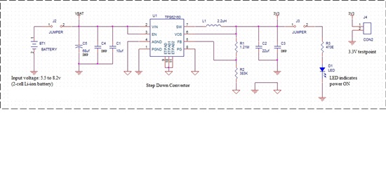
    Please find below our schematics. To save the IC from overshooting voltage I have put an ESD diode in place. Can you please review the schematics and give your feedback. TPS62160 looks good.  

  • The input esd diode should help with any input voltage transient spikes.  Please measure Vin at the IC on your board to confirm you do not have a problem.  Be sure to exactly follow the EVM layout to minimize the possibility that you have a layout problem.  Input cap is most important component.  I did not review your component selection; I assume you followed the datasheet recommendations when selecting them. 

  • Hi Michael,

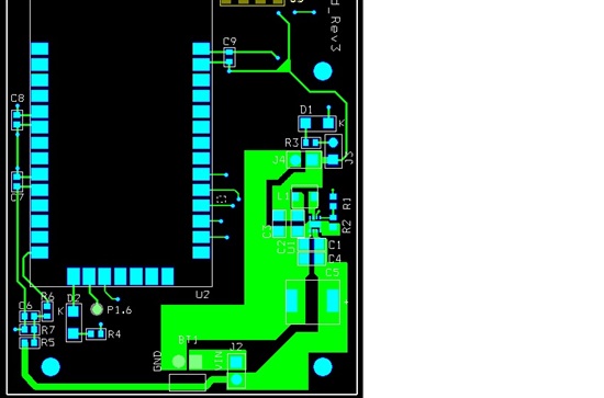
    We did our design for the power board using TPS62160. I followed the schematics and layout recommendation as provided in the evm. I am facing a very strange issue. The output voltage of my board is not stable, it is continuously varying from 3.2 to 5v at no load. The voltage at FB is also varying.

    As soon as I connect the load (LED) at output, output voltage stabilizes a bit and varies between 3.9v and 4v. It should ideally be 3.3v. 

    Please find below schematics and layout of my board. 

    What can be the possible issue? Please help me out. 

    Thanks and Regards,

    Aziz Jiwani

  • I do not know the other customer's final resolution. They did not reply with what they did to solve their problem.  I would like to recommend that you contact your local FAE in India.  They will be able to work directly with you understand the waveforms and help find the problem.  Without actually seeing scope pictures of the relevant waveforms, it is very difficult to know what is going on.  You local disty FAE should be able to go into the lab with you to help you with these measurements.

  • Hi,

    I figured out the issue. I have made a mistake of connecting PG to GND. 

    I tested the board again after cutting the track between PG and GND. Regulator is working fine (output: 3.3v) with PG floating.

    Do I still need to connect it a pull up resistor for efficient working or floating PG is fine?

    Awaiting reply. 

    Thanks and Regards,

    Aziz Jiwani

  • If TPS62050 PG pin is unused, connect to ground or leave floating.