This thread has been locked.

If you have a related question, please click the "Ask a related question" button in the top right corner. The newly created question will be automatically linked to this question.

TPS62130A overshoot of output voltage at powerup

Hi

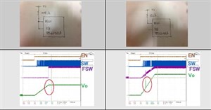
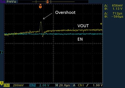
The overshoot has been confirmed to the output when a customer evaluated in the circuit, such as the following.

It does not occur when it is used in fsw=2.5MHz mode , however it occur when the frequency is set 1.25MHz.

We guess the overshoot has occurred when the frequency is changed at powerup.

Is it normal behavior. Are there any solution for this phenomenon if it is not.

(condition)

  Vi=10V, Vo=1.8V,Io=1.6A, fsw=1.25MHz

(additional information)

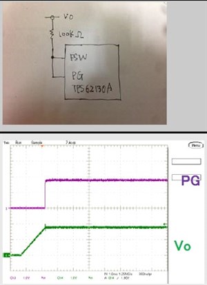
These phenomena are seen in the board of the customer, I have also seen your EVM which is connected with a lead wire FSW terminal and terminal PG further.

Best Regards,

Koji Hamamoto

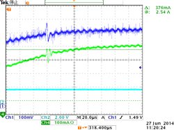
  • It looks like you connect the FSW pin to either Vout or PG.  This is correct.  There should be no overshoot.  Here is what I see on the EVM: 8244.TPS62130A_1pt6A_load.TIF

    Could you provide a zoomed in plot of Vout and the inductor current when the output voltage rises?  I cannot read the timescale of the scope plots, but it may be simply noise picked up by the probe if it is very fast.

  • Hi Chris-san

    Thank you for your great support,

    This is what was measured in the TI-EVM.

    I think this is not simply spike noise by probe. 

    Regards,

    Koji Hamamoto.

  • Is it possible to obtain the inductor current or SW pin at a small timescale (5 usec/div) when the spike occurs?  Having this would show if it is noise or not.

  • Hi Chris-san

    I appreciate you support. 

    I will try to get the waveform that you asked.

    However,do you have any guess this cause?

    regards,

    Koji

  • Thank you.

    This looks like noise.  The spike is very narrow.  As well, no one else has seen this behavior, so it must be test setup related.

  • Hi Chris-san

    Thank you for your quick reply.

    I will get the waveform what you asked. But this spike is a reproducible.

    Regards,

    K

  • Hi  

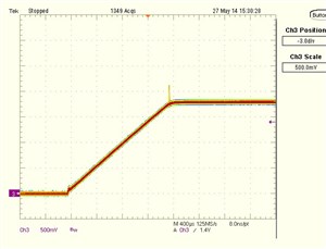
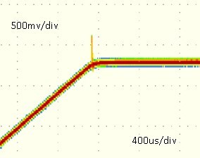
    I got a waveform which is zoomed as you asked

    .

    This is what was overwritten continuously measured waveform.

    There is a reproducible this phenomenon. This occurs only when the fsw=1.25MHz further.

    Regards,

    Koji Hamamoto

  • I am sorry but this does not help see the spike any better.  

    I would like the inductor current added to the scope plot.  If this is not possible, the SW node may tell us something.

    As well, I would like to see a new scope capture, taken at 10usec/div.  We need to assess the pulse width of this overshoot and be able to measure it in usec.  This is not possible with the current waveform.

    Could you explain your test setup?  Is an electronic load used?

  • Hi Chris-san

    I appreciate your great support.

    It's to get the waveform that you have requested is difficult. Because these waveforms is because waveform by the customer measurement. However I will try.

    The power supply is connected to the input , EN signal is repeatedly On/Off by the external clock generator(Fenable). The load uses the electronic load further.

    Vi=10V, Vo=1.8V,Io=1.6A, Fenable=1Hz, Fsw=1.25MHz

    Again, thanks to the kind support.

    Regards,

    Koji Hamamoto

  • Thank you for trying.

    Your test setup seems normal.  Could you provide the duty cycle or on time of the applied EN signal?

    Electronic loads sometimes cause issues to appear that are really a result of the electronic load and not the circuit.  This may be one such issue.  Their active control loops, typically lengthy connections, ability to pull the output below ground, etc. sometimes combine to show odd behavior.  Would it be possible to retest with a resistive load and/or the electronic load put in constant resistance mode?

    I used an electronic load in my testing and did not see an overshoot, but different ones behave differently.

  • Hi Chris-san

    I appreciate your kind advice. 

    I got the waveform with the help of the customer board as you gave me advice.

    It was not observed the overshoot as measured in CC mode of the electronic load. However it  was observed the overshoot in CR mode. 

     Please see below the waveform.

    1. Vout and PG (in CR mode)


    2. Vout and SW node (in CR mode)

    Why does this phenomenon occur only in CR mode.

    Best regards,

    Koji Hamamoto

  • Good debugging!

    This does not seem to be noise.  Rather, it seems the load somehow causes this.  To understand exactly why, it would be necessary to measure the inductor current and load current with current probes at the 2 usec/div timescale.  There is possibly something in the load changing at that time which affects the current drawn into the load.  This basically applies some sort of load step to the output, for which the output voltage responds accordingly.

    But we have seen no other reports of a startup overshoot with these devices, so I am confident that this is purely related to your test setup.

  • I appreciate your great support.

    I agree with your comment which the cause is related to test setup.

    I will evaluate as your advice. And I will let you know the result.

    Regards,

    Koji Hamamoto

  • Hi 

    I am sorry for not replying.

    I got a waveform which is output voltage and load current. Does it make sense?

    I will try to get another waveform if it does not.

    Regards,

    Koji Hamamoto

  • Yes, this helps.  The output current is changing even though you have the electronic load set to pull a certain amount of current.  This and the test you did that using a resistive load eliminates the spike proves that this is a test setup issue.

  • Hi 

    I appreciate your quickly support.

    I have one question that I would like to ask.

    I understand that you explained, but why does it occur at the point where the frequency is changed.

    And this phenomenon does not occur when a capacitor (2200pF) is added between AGND and FSW.


    Regards,

    Koji Hamamoto

  • Ah, this is a new detail.  Was FSW connected directly to Vout or through a resistor?  Was the electronic load in CR mode used for that test?

  • Thank you for your replay.

    Could you refer my the first and second posts about the other detail.

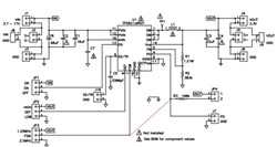
    The FSW connected to Vout via resistor. Because the parasitic capacitance on PCB pattern.

    Please see following circuit.(red line)

    The electronic load was in CR mode used for this test. But it does not occur this phenomenon if the capacitor(2200pF) was connected between FSW and AGND.

    Regards,

    Koji 

  • Hmm, I have never heard of this behavior happening but it seems that your load does not like the frequency applied to it changing.  I'm not sure what could cause the load to behave this way.

    I checked our EVM again here and see no disturbance when the FSW pin goes high and the frequency changes.

  • Thank you for your support.

    I summarized all detail for this issue. But there include some confidential information of our customer.

    Can we talk with email?

    I will send the information to you if we can.

    Regards,

    Koji