This thread has been locked.

If you have a related question, please click the "Ask a related question" button in the top right corner. The newly created question will be automatically linked to this question.

LM5001 Sepic converter

Other Parts Discussed in Thread: LM5001, LM5022, LM3478

Dear TI community and experts,

since LM5001 is not supported by the WEBENCH Designer, i can not find any document describing the best values for external components. Is there really no design guideline available?

I need a wide range imput (9-60V) and 12V, 250mA output, similar to an SEPIC application example given in the LM5001 datasheet but with higher current.

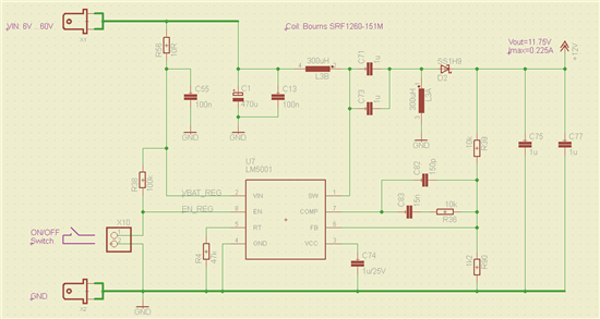
I've tried to simulate the circuit as given in the datasheet, using the model delivered with the startup testbench. But the circuit is not working properly. See the attached image of the circuit.


Best Regards,

Florian

  • Hi Florian,

    The EN pin can be connected to an external voltage divider to set adjustable UVLO. If you don't need the adjustable UVLO, you can just leave it open since there is a internal 6uA pull up current source that will pulls the EN pin high to enable the device. Also, the abs max voltage rating of EN is only 14V, so it can not be connected to VIN when max VIN is above 14V.

    I noticed that you are using the exactly same schematic as the design example in the datasheet except the EN pin connection. Please let me know what specific question you might have, and we can help you from there.

    Thanks.

    Haifeng

  • Hello Haifeng,

    I've connected the EN pin because the netlister complains if it is left unconnected. According to the datasheet a pull up current of up to 4mA is allowed, so it should be OK.

    My questions would be:
    1) which external components are required to achieve a wide input range (9-60V) SEPIC with 12V, 250mA output?
    2) what are the input voltage limits for the desired output (e.g. is 6V-75V possible, too) and why?
    3) how are the external components for a SEPIC converter calculated?
    4) any idea why the simulation does not behave as expected?

    Thanks in advance & Best Regards,

    Florian

  • Hi Florian,

    You can refer to the article (http://www.ti.com/lit/an/slyt309/slyt309.pdf) to design the external components for a SEPIC converter.

    The max conversion ratio is limited by the max duty cycle. LM5022 has an typical 95% max duty cylce, while the min max duty cylce is 90%. The converison ratio of a SEPIC converter in CCM is expressed by:

    M=VOUT/VIN=D/(1-D)

    For 6V to 75V conversion, the required duty cycle is :

    D=VOUT/(VIN+VOUT)=75/(6+75)=92.59%

    So in worst case where the min max duty cycle of LM5022 is 90%, 6V to 75V conversion might not be achieved.

    Thanks.

  • Hello Haifeng,

    thank you very much for your help so far.
    With "slyt309.pdf" I was able to dimension a SEPIC design for the LM5001 that generates 11.75V at 225mA from a 6V to 60V input range. Unfortunately the regulator creates audible noise. The reason might be instability of the regulation. Here is the circuit:

    Measuring the output (blue) I found a 2Vpp noise in the audible frequency range. The SW pin (yellow) shows interrupted operation. The operating conditions are 6V input and 35mA output current.

    Obviously something is wrong here. Can you please help me!?
    Maybe the compensation network ins not optimized. I did not find any hint how to dimension it in "slyt309.pdf".

    Best Regards,

    Florian

  • Hello,

    It look likes you are indeed unstable.  Please try the following values.  

    R36 change from 10k to 1k

    C83 Change from 15nF to 220nF.

    Hope this helps?

    David Baba.

  • Hello David,

    thank you for the values, now the regulator is stable.
    Unfortunately I observed an overswing on power up and in case of load drop. I already increased the output cap to 10uF.
    Can you give me further hints how to dimension the feedback network. I found in "AN-1484 Designing A SEPIC Converter.pdf" the equations for the LM3478. Is there something similar available for the LM5001?

    Best Regards,

    Florian Brugger

  • Hi Florian,


    Please follow the guidelines for increasing start up time found in the LM5001 datasheet on page 13; Figure 17.  By using this circuit you can tune a longer start up time, the longer the start up the less the over swing.  Increasing Cout definitely will help also, I did note that your selected Cout was untypically very small; recommend 10uF's (47uF) will certainly help a little.

    Regarding an Application Note, unfortunately there are none for the LM5001 in a SEPIC configuration.  I will say though, deceasing Rcomp ensures a lower cross over frequency and most of the time remedies any Stability issues in a SEPIC (and other Fixed Frequency PWM Topologies).  In the case of a Buck Boost/Boost this is typically because you have a Right Half Plane Zero (RHPZ) to contend with.  The RHPZ exhibits a Gain increase and a Phase Decrease.  The decrement in phase shift at cross over will typically result in an unstable loop and the only remedy is to cross over at a lower frequency (lower Bandwidth - BW).  Having said this, you may be able to increase your BW a little, as the loop although now stable, maybe a little sluggish; you can do this empirically by gradually increasing and tuning Rcomp.  But the first thing I would do is use the soft start circuit.

    Hope this helps?

    David Baba.

  • Hi David,

    thank you for the hints! 
    I found out that the switching frequecy has an impact on the regulation behavior, too. So I increased it to 570kHz. By tuning Rcomp, as you suggested, I managed to reduce the transient overswing to less than 10%. So I do not even need the softstart function.

    Thank you for your support and have a great day!

    Best Regards,

    Florian Brugger