This thread has been locked.

If you have a related question, please click the "Ask a related question" button in the top right corner. The newly created question will be automatically linked to this question.

TPS63020 symbol error

Other Parts Discussed in Thread: TPS63020

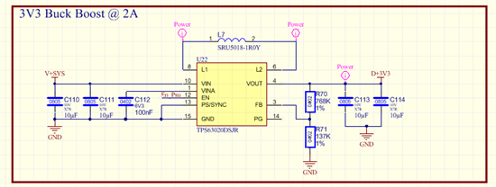
I am quite embarrassed, but I managed to make an incorrect symbol for the TPS63020. For the L1,L2,Vin and Vout I only use 1 pin of each pair of pins.

L1 = 8

L2 = 6

Vin = 10

Vout = 4

The feedback resistors are 768K and 137K to give 3V3

When the unit powers up, it does not seem to regulate, i.e. with input of 3V I needs to boost to 3V3 but it boosts to 4V7, causing high current draw from my 3V3 chips on the 3V3 rail.

My question is whether the chip will function like this, understanding that the current capability would be impaired. I can obviously modify the PCB to have these pins connected on the current boards, but it is a major mission to do.

Can an expert on the TPS63020 internals perhaps shed some light on my problem?

Regards

Ivor

  • Your circuit most likely will be funcional with only one pin each of the LX pin pairs connected. The pins are connected internally. The internal current distribution will be worse as well as the thermal performance of the package. This affects reliability.

    I don't know what the current boards are used for, so it may not be a big issue. For a final production version I would recommend to change the layout.

  • Juergen, thanks for the confirmation. I will update for the production boards.


    Ivor

  • Below is my INCORRECT schematic, with the symbol errors

    V+SYS ranges from 3V to 4.2V. En_Psu is pulled up to V+SYS.

    With this setup below, pins left open, the regulator pushes out 6.7V to my 3V3 cct. Any ideas why that would be? Checked the feedback resistors, they are connected fine and in the right sequence.

    Just to make sure you saw it initially, the Vin and Vout also use single pins, not only the L1 and L2 pins.

  • 6.7V may indicate that the output overvoltage protection of the TPS63020 is controlling the output.

    This will happen when the output voltage of the TPS63020 is not fed back properly to the FB pin. Wrong resistor values or broken connections can cause this. Another option is using a fixed output voltage version in a design which has been done for the adjustable version.

    Another possible root cause may be power coming from another power supply connected to the 3.3V rail at the output of the TPS63020.

  • Hi Juergen,

    OK, so I just refitted a new TPS63020 to my board (with the single pin problem as explained above). I measured each track for connection to the chip pin, specifically focusing on the feedback resistor pair. All is good, but on switch on, the regulator is still just passing 6.7V through to 3V3 rail.


    Are you sure that the other Vin and Vout pins are not required to be wired for the device to operate properly, perhaps the internal circuit only uses Vin/Vout that is not wired for something?

    I removed the "verified" tag from a previous answer, not because I think you are wrong, just because I could not verify it.

    Next Steps:

    1. I already had pins 6 and 7 for the inductor shorted for the test above, result = 6.7V output

    2. Added a short between pins 4 and 5, results still 6.7V output. The Vfb = 934mV. This chip should regulate the output down for a 500mV via divider here, but it does not.

    3. Added short (with a lot of struggle...its amazing how difficult it is to make a short on purpose) between pins 10 and 11. Result is the same, 6.x V on output.

    4. The PCB is now exactly the same as the dev kit in terms of pin usage. I have placed shorts where they need to be to connect the unconnected pins. I have even replaced the feedback pin resistors with new one, replaced the inductor (SRU5018-1R0Y out of desperation), but still the output is 6.7V.

    All the steps above are done with the new chip placed.

    For the record, if I remove the chip and connect a lab power supply of 3V3 to the output, the board powers up correctly, drawing the expected 200mA. There is no other supply feeding into this point.

    Please, ANY ideas are welcome.

    Ivor

  • Can you try to short R70 (short between FB to VOUT)?