Hi,
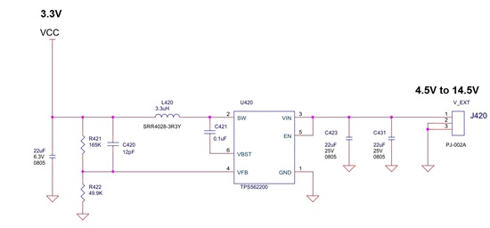
I am working with TPS562200 per the attached design.
Vin: 12V
Vout: 3.3V
Iout: 100mA
Can someone suggest an explanation for 10% of my boards that got burned?
This thread has been locked.
If you have a related question, please click the "Ask a related question" button in the top right corner. The newly created question will be automatically linked to this question.
Your resistor divider values are too high I would recommend 10.0k for the lower, then calculate the upper from that. C420 should not be used. Are you hot plugging the input voltage? Layout is also critical.
High impedance FB resistors can lead to noise in teh control circuitry and possibly allow for shoot thru between high and low side FET. I do not know if the feed forward cap contributes to this effect, but we do not recommend it anyway as the regulation will be poor, so you should not use it.
Hot plugging VIN can cause transient voltages up to VIN x 2. This over voltage can damage the IC and cause high and /or low side FET to short.
Poor layout can contribute to either effect.
"Hot plugging" Is directly applying Vin to your circuit by connecting Vin to the circuit while Vin is present vs connecting your Vin supply when Vin = 0 V, then allowing Vin to ramp up from 0 V to Vin at some normal ramp up time, usually in the range of a few msec. Hot plugging can cause voltage transients up to Vin x 2 which can exceed the abs max and damage the IC.
I also see that you have a long return path from your input cap to ground. That may be your issue. Try connecting the ground side directly to your ground pin 1. You can temporarily jumper it with a short heavy gauge wire.
Thanks a lot for such a prompt response during weekend!
We have only one source of external Vin. When circuit is not powered we may only have the residual voltage of input capacitors.
Cin has vias directly to GND in layer #2 (PCB has 4 layers).
BR
Gil
The blue ground copper wraps around to get from the input cap to pin 1. It should be a shorter path. On the reference design, the input caps are connected to VIN and GND directly on layer 1, while the SW node is routed on the bottom. You might want to try grounding the cap on the top side with a short wire.
Can you take a waveform of Vin when you apply power? look for any over voltage conditions.
I think that 24 V peak may be enough to damage the IC. You will need to do something to clamp it or possibly reduce the rise time.
I tested 40 circuits after changing resistors and cap. All board worked fine with and w/o protection diode (16V Zener).
I was not able to reproduce the fault, even by getting the old resistors and cap back. Since not all of our board had this issue from the beginning, I am not 100% sure that we pointed the root cause.
Do you have experience with TPS562200 that burned due to high resistors and/or Cff ?
There have been some reports of failures. They may be correlated to high FB resistor values, but I think it is not definite. In any case we are recommending lower values to be safe. In your case, I would think that the input voltage spike is your real issue.
Dear John,
We followed your recommendations: 10K resistor, no cap between VFB and SW, VIN overshoot < 17.5V.
We have much less fault incidents, but we still get some ICs that got burned few seconds (or minutes) after power-up.
Vin = 12V, Vout = 3V, Iout < 50mA.
My questions are:
1. Is it possible that touching the device with bare hands is the root cause?
2. Do you have any other suggestion?
3. Is it better to use TPS563200 or TPS562209 instead of TPS562200?
Thank you in advance and happy new year
Gil
Hello,
I am having the same issues with this part. I originally thought it was an ESD issue. I burned out 5 boards in a row. The board would work fine sitting on the desk, but then if I touched anywhere on the board it would fry. After replacing the parts it seems fine now. We have a couple dozen boards running. Maybe there's an intermittent oscillation happening. I notice that if I touch the circuit w/ my finger I can get the part to fry, even if I touch the FB pin with my 1M scope probe.
Here's my circuit below, power is ORed through two schottkey's from either 7.4V from batteries or 15V from a boost converter. I've tried unpopulating the phase cap, and tried increasing to 10pF. If I hold my finger or probe at certain points in the circuit, I can audibly hear the inductors start to hiss, not sure if this is a clue.
Another behavior I noticed is that the regulator would shut down intermittently, seeming depending on the stray capacitance/resistance it was presented by the case.
Temperature environment is normal room temp, but it's been hot in NY the past week, so maybe that's affecting something?
TPS562200 has been revised with reliability enhancements. These new parts are functionally and parametrically identical. One thing that can help with old parts is to use lower value FB resistors, less than 10k ohm.