This thread has been locked.

If you have a related question, please click the "Ask a related question" button in the top right corner. The newly created question will be automatically linked to this question.

TPS62561 PFM mode

Other Parts Discussed in Thread: TPS62561, TPS62230, TPS62740, TPS62560

I am using the TPS62561 (the TSOT-23 package that does not have a mode pin)  in a small design.  It seems that when there is no load on the unit, it will drain the batteries (providing power to the TPS62561) faster than with a load on the unit.

I thought that the without the mode pin the PFM operation would be enabled all the time but it seems like the PFM is DISABLED in this package.  And I do not see any comment on the DS about which way PFM is configured in this package.

(Unfortunately I haven't had a chance to scope it yet to check as the circuit is at another location.)

Any comments would are appreciated!

Thanks,

Kurtis Unger

  • Yes, PFM mode is enabled on this device.

    I don't understand what you mean when you say your batteries are drained faster with a load than without one.  Where is the load?  How much power does it draw?

    The newer TPS62230 and TPS62740 would be recommended.

  • Hi Chris, 

    Thanks for the quick reply.

    The full setup is:

    Solar panel -> LT Solar charger -> 4.1V @ Battery -> TPS62561 -> 3.3V @ Sensor/GPS

    We did some testing where there was NO Sensor/GPS hooked up at the output of the TPS IC and in this case the battery drains faster than expected.  (It appears to be draining even faster than with the Sensor/GPS connected.)  Which had me look at the no load response of the TPS device.  Unfortunately the devices are all out in the field and I do not have one with me for further testing but I will try to get one by the end of the week.

    I will look into the TPS62230 / 740. 

    Full disclosure, I am located in Nairobi, Kenya so getting a hold of and testing new parts is not easy.  I also do not have a local TI rep that I can interface with so that also slows things down.

    Thanks again for your input.

  • Hmm, there is something else going on with your system when the load is not connected.  There will always be more power drawn at the input to the TPS device with a load than without one.

  • Hi Chris,

      OK thanks for that information.  The main thing I wanted to confirm was that PFM is enabled with the TSOT23 package.

      I'll see what else might be going on.

    Kurt

  • Hi Chris,

      So the end user was able to confirm that the TPS62561 draws about 2mA with no load.  I have a couple of boards in as well and have confirmed this.

      Even though my layout is pretty bad (in looking into this I've found a number of things I could have done much better!) I don't see how it could be drawing that much current.  The output is fine, with very little ripple, even on light load.  (Though I will be doing some more evaluation.)

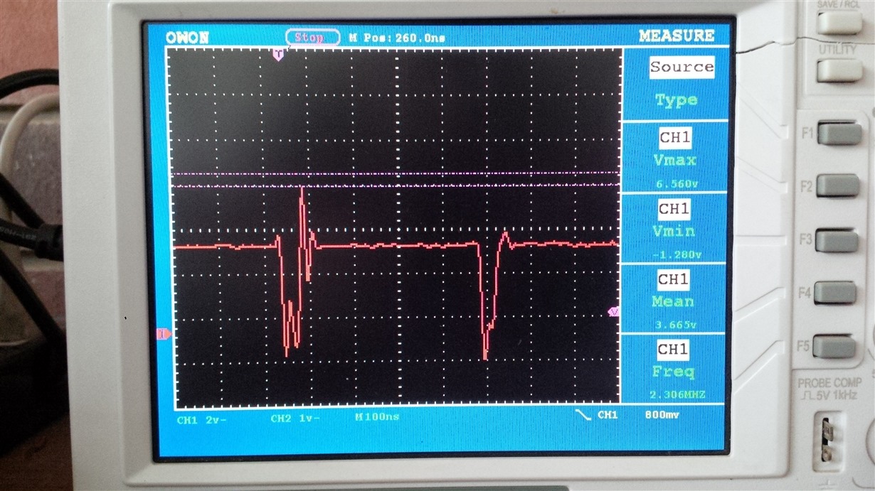
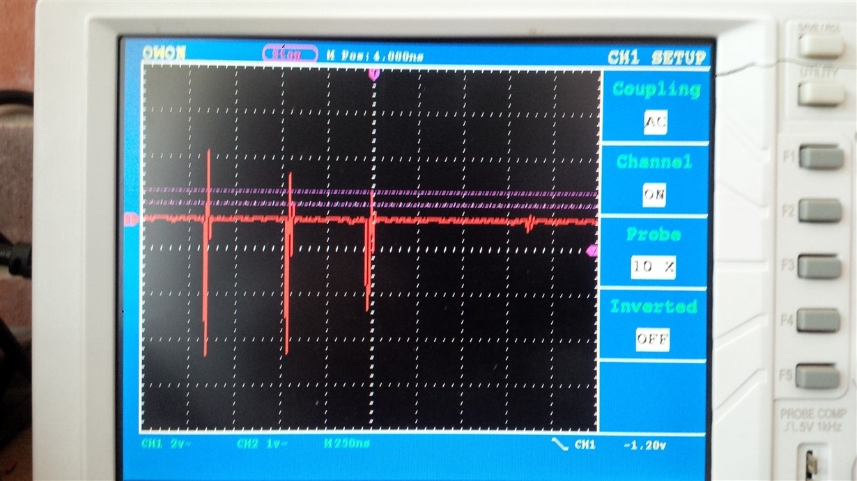
      I've attached a scope capture pic of the switch pin (5) on the switcher (recall I'm using the TSOT23 package) with no load and with a 360mA load.  (See below) They are not what I would expect from the various figures in the datasheet.

    Some things to note

    - the output is set to about 3.6V - I think this is a little on the high side for this part - any comments?  (The resistor pair is 915K and 180K which has a sum greater than 1M which I realize is not ideal.)

    - the layout has a small connection (12mil trace) to for the connection to Vin as well as from the base of R1 (180K) to the ground of the chip due to bad layout.  I've fixed these up manually but it doesn't seem to change the behavior of the board.  (Again I will evaluate more.)

    Any ideas at all as to what might be creating this current draw?  (I've ohmed out the boards and there isn't any noteworthy continuity between the output and ground.)

    I can provide my schematic and layout if that would help.

    Thanks so much,

    Kurtis Unger

    No Load

    360mA load

  • I recommend ordering the EVM for the TPS62560 and testing with its known good layout.
  • OK thanks for your support.  

    Note I would like to use the TSOT23 part (the EVM and the DS both provide layouts for the SON part) for easy of manufacturing (these are hand placed and then re-flowed here in Nairobi) and have not been able to find a recommended layout for that part.  I made some obvious tweaks to the layout and it's very good now I just wanted to get your ideas before I went and ordered new boards.

  • The SOT23 layout should be very similar to the SON as the pin locations are the same. If you post your layout here, I can check it.

    The SW node waveform you captured doesn't look right.