This thread has been locked.

If you have a related question, please click the "Ask a related question" button in the top right corner. The newly created question will be automatically linked to this question.

TPS65400 not regulating

Other Parts Discussed in Thread: TPS65400, USB2ANY

I'm currently trying to bring-up a new design, but am having some difficulty with the TPS65400. We've design this particular supply to that two of the rails will turn on automatically, while the other two are enabled by an FPGA later on. The intent of the design is to work as intended without the need to program the controller, ie it should work stand alone. Here are some waveforms to help illustrate what we're seeing:

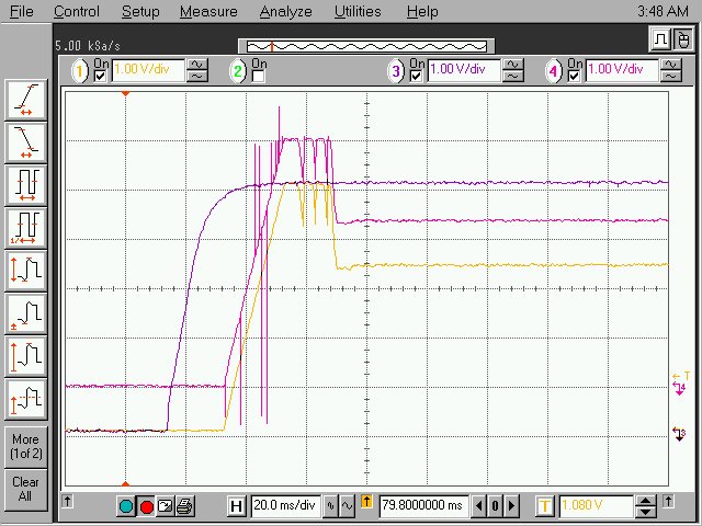
This screen capture shows the 5V input (purple), 3.3V output (yellow), and the 3.3V SW node between the TPS65400 and the inductor (pink). There are a few things to note here:

1) 5V turns on cleanly
2) The 3.3V rail overshoots the 3.3V set point and reaches 5V on when powering up
3) The 3.3V rail settles at 3.3V after some time
4) The 3.3V rail SW node never appears to switch, but looks as if it is regulating linearly

I tried putting some extra loading on 3.3V and noted that the output voltage decreased to 3.1V, so it appears that the 3.3V phase is not actually regulating.

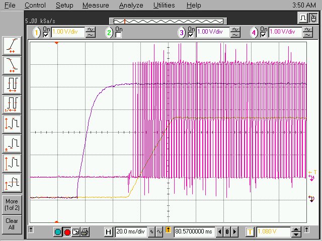
This image shows the other phase that should turn on automatically. It is a 1.5V rail. In this image the rails are represented as follows: 5V (purple), 1.5V output (yellow), and 1.5V SW node (pink). Note that:

1) 5V turns on cleanly
2) The 1.5V output actually regulates to 3.5V
3) The 1.5V SW node switches as expected and the Pulse Width increases as expected for soft start

I measured the feedbank pin for this rail with a volt meter and found it to be 1.866V, so it appears to me as if Vref is set to 1.87V, but again, we haven't done any programming of the part, so I expect Vref to be 0.8V.

Please let us know how this behavior may be explained, and what else we can try or look at to solve the problem. I'm attaching the relevant schematic page from our design.

Please note that we would like to solve this problem quickly.

Thank you for your help.

Best Regards,

Kevin

TPS65400.pdf

  • UPDATE


    After another day of experimenting we've discovered the following:

    We were able to communicate over PMBus with the TPS65400, but we didn't use PI-Commander. I do have a USB2ANY device, but please note that we don't bring the following signal out to the our header:

    RST_N
    CLK_OUT
    SYNC
    EN1-4
    I2CADDR

    I'm not sure what PI-Commander is expecting, but it doesn't find any devices during it's scan. We were able to communicate with the TPS65400 using Digital Fusion Power Designer software. It doesn't target the TPS65400, but we were able to get it to boot using a different board with a UCD device and then move the USB-to-GPIO tool to the TPS65400. In this way we could use the raw PMBus access features of Fusion Designer. We read several register including the Vref of all 4 phases on the TPS65400. All 4 Vref values were 0x7F. We were also able to program the Vref values for the two enabled rails to 0x14 and both rails began to function as expected. (ie 1.5V output was at 1.5V and the 3.3V SW node began switching.) We also tried communication with another TPS65400 on the board and found its Vref values to be 0x7F as well. I hope we can find an explanation for this. Please note that we were able to successfully program the internal flash with the correct Vref values, so now when our board is power cycled, we see both rails operate correctly.

    Please note that we have four TPS65400 devices on the board in total. Today I intend to try to read the full configuration of all these devices to verify if the registers are at the correct default values. (Our designs are based on defaults.) I'm using a third party I2C tool for this, since Digital Fusion Power Designer only allows me to communicate one transaction at a time and PI-Commander won't communicate at all. I would suggest make PI-Commander capable of communicating with only the SCL and SDA signals, since many embedded designs may not make available all the signals listed above. (If there is a way to make PI-Commander work in this manner, please let me know.)

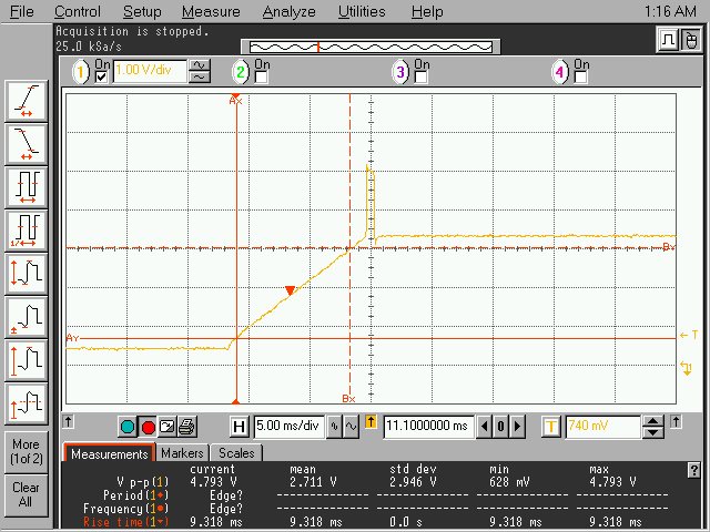
    We measured the 3.3V rail does show one continuing issue. Please refer to the following waveform.

    As you can see the turn on ramp appears normal and seems to ramp nicely to 3.3V, but then spikes temporarily to 5V. We would appreciate any insight as to what may cause this issue.

    Thanks again for all your help.

    Regards,
    Kevin

  • Hi Kevin,

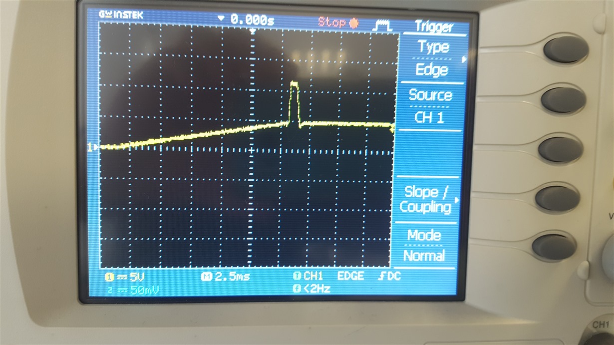
    We have a very similar problem on our project. As you can see, also we have a spike on the 5V rail (it goes up to 12V):

     Pleasenote, that the spike is not present on all boards.

    Were you able to fix this problem? 

    Thanks.

    Kind regards,

    Mit