This thread has been locked.

If you have a related question, please click the "Ask a related question" button in the top right corner. The newly created question will be automatically linked to this question.

LM3485 Problem

Other Parts Discussed in Thread: LM3485

Hi All!

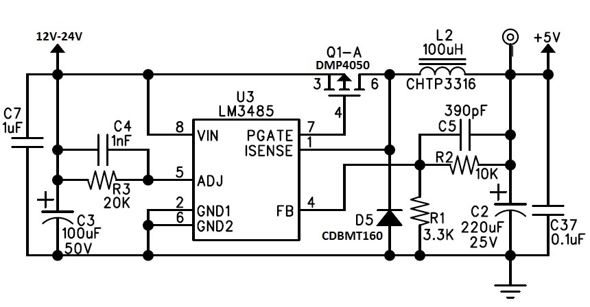
I have been using the LM3485 for over 10 years with this same circuit (different output voltage but other than that just the same), yesterday I got this new board

and nothing, the circuit just oscillate and I 'get' 1.7V on the output! what is going on?

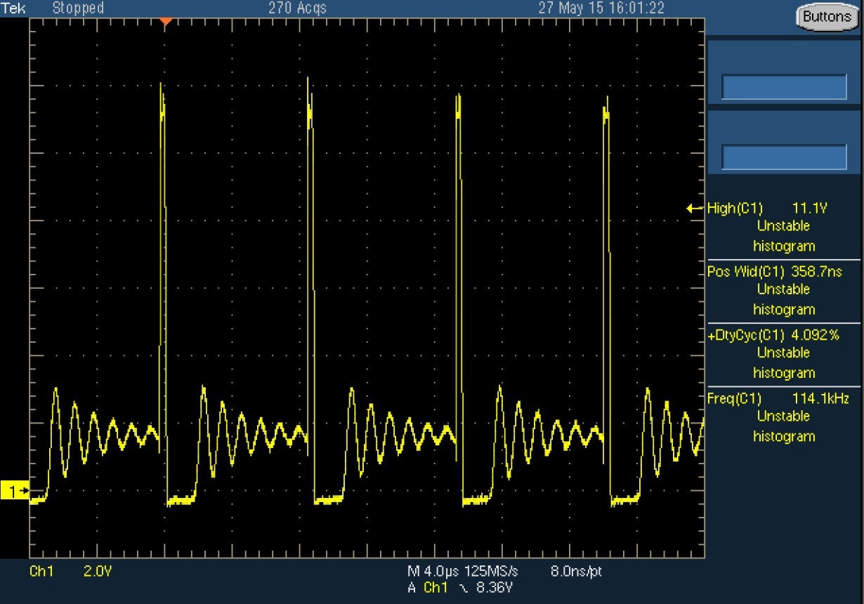
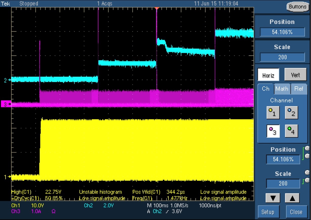
this is what I see on U3 pin 1 :

The capacitors are aluminum but changing the output capacitor to 100uF tantalum didn't help.

For years this circuit was 'bullet prof', I tried every thing I could think of to make it work without any real success.

What am I doing wrong here?

Many thanks

Omer Zeharhary

AMI

  • Hello Omer,

    What is your output load current? What is the C2 ESR resistor value. It seems  from the SW node waveform that the part here is entering into a discontinuous mode of operation. Also during the on time the  VIN seems to be less than 12V (at the switch node). 

    I am assuming all other components are perfectly soldered. Are all the components on this board same as you have been using in your previous boards?

    If possible add an extra ESR resistor in series with the C2. It is possible the electrolytic cap doesnot have enough ESR for stable operation. Another approach would be to try reducing the filter cap, Cadj to say 100pF. It may be so the time constant of the Radj and Cadj filter is more than what is required during the intial current sensing.

    Please check the P-FET connections as well.

    Regards,

    Sourav

  • Sourav Hi!

    Thank you for your response and time.

    The load current is changing between 0.1A to 0.7A and the input voltage is 12V or 24V.

    Maybe I wasn't clear on this but this is not an new design, it's a board that came from production for approval of assembly!

    Old production and hand assembly versions worked (and still working) fine... that's the main problem.

    I got some results by changing C2 (the output capacitor) with the same value capacitor from a different company but it not good enough, I still

    have problems with performance and reliability.

    Thanks again

    Omer Zeharhary

    AMI

  • Hello Omer,

    Have you tried replacing the IC with another LM3485 IC?
    Can you replace the IC and try it your older board version. I am just trying to separate the issue between the board and the IC.
    I can't spot any issue with the circuit. However, I will still try the previous cases in case it helps.

    Regards,
    Sourav
  • Sourav Hi!

    Thanks for your answer.

    During the last few days I have replaced so many damaged regulators it just sad...

    I think I can identify two kinds of failure :

    1. Few regulators just don't give enough 'juice' so on power up when the board CPU start running the voltage begin to drop until the RESET chip hold the CPU

       and the regulator manage to recover the voltage. and so on in infinite loop...

    2. Some regulators work fine with 12V input voltage, they work fine even when I manually raise the input voltage to 24V, however when I try to start up the board

       on 24V the regulator break down. The 'magic' voltage is actually 22V! Anything below is fine.

    When the regulator fail it does in one of two ways, it either stuck completely or it oscillate at 118KHz.

    Many Thanks

    Omer Zeharhary

    AMI

  • Hello Omer,

    What is the ESR of the output electrolytic capacitor? What is the C2 part number you have on board. Can you take out C37 once and check the board again. When you say damaged do you mean you have parts blowing up or simply it fails to operate as you expect? Do you have a DS for the inductor?

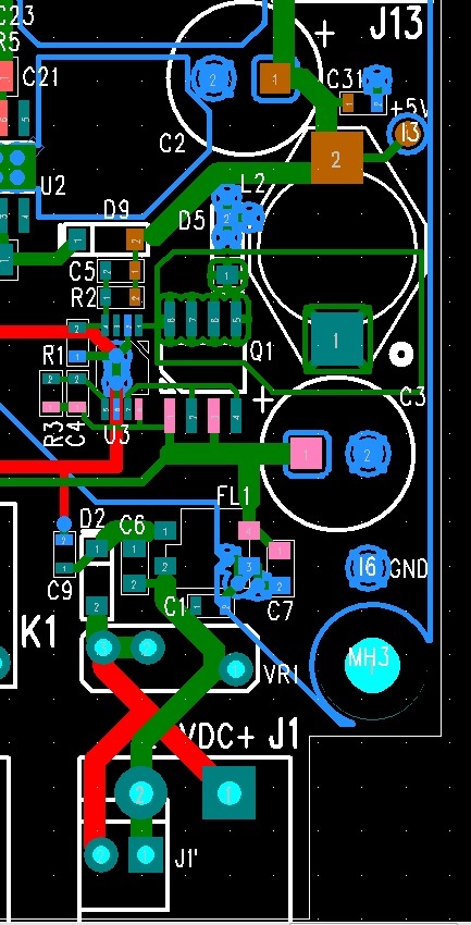
    Can you share your layout files of these new boards? Are they different from the old ones. I am beginning to suspect there might be some issue with the layout.

    I am still not sure how the parts can behave so differently in these 'new' boards. Did you try these 'new' samples of LM3485 in your old boards which you said have been working without any issue. Are the old working EVMs failing with these new LM3485 samples as well ?

    When you get a chance please verify that as that it will help to separate the issue between the parts and boards.

    Regards,
    Sourav
  • Sourav Hi!

    The Components I used :

    C2 - http://www.digikey.com/product-search/en?x=20&y=16&lang=en&site=us&keywords=P12383-ND.

    L2 - http://www.digikey.com/product-search/en?vendor=0&keywords=553-1067-2-ND.

    D5 - http://www.digikey.com/product-search/en?vendor=0&keywords=641-1444-2-ND.

    The failed ICs didn't smoked they just stop working right.

    The board main power supply area, Green = Top, Blue plane = bottom, Red tracks = Bottom, it's a 2 layer board:

    The new PCB only really minor changes around the power supply area compare to the 6 months old (working) version.\

    I'll try some more components switching with the old boards.

    Many Thanks

    Omer Zeharhary

    AMI

  • Sourav Hi!

    The Components I used (I can't attach the datasheets themselves, sorry.) :

    C2 -DigiKey P/N: P12383-ND.

    L2 -DigiKey P/N: 553-1067-2-ND

    D5 -DigiKey P/N: 641-1444-2-ND

    The failed ICs didn't smoked they just stop working right.

    The board main power supply area, Green = Top, Blue plane = bottom, Red tracks = Bottom, it's a 2 layer board:

    The new PCB only really minor changes around the power supply area compare to the 6 months old (working) version.\

    I'll try some more components switching with the old boards.

    Many Thanks

    Omer Zeharhary

    AMI

  • Sourav Hi!

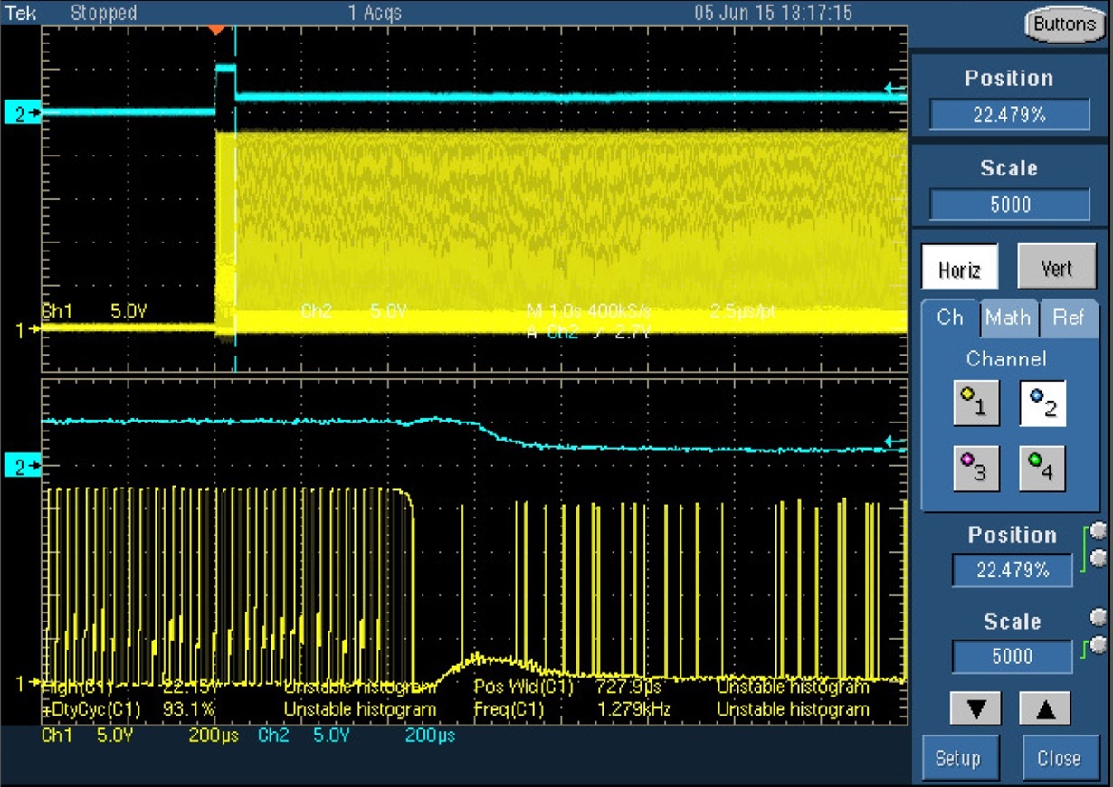
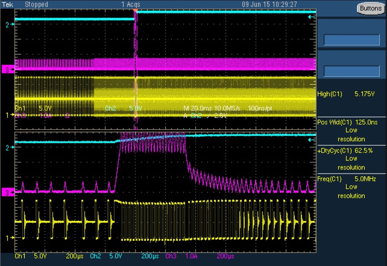
    I did some more tests and I got a scope screen dump of the moment of failure.

    On that moment the CPU activate the cellular modem and increase the load on the PS.

    In the picture the blue is the PS output (5V) and the Yellow is the voltage on the cathode of D5.

    What do you make of that?

    Many thanks

    Omer Zeharhary

    AMI
  • Hello Omer,

    Thank you for the waveform.
    When the modem is activated, do you expect a load of ~0.7A to be drawn as load?
    According to the formula given in the DS for the current limit calculations, the worst case current limit value can be 0.76A for the components you have on board.
    The SW node waveform here post loading the part seems different from the one which you had posted at the beginning. Are they two different conditions?

    Will it possible for you to probe the inductor current in your circuit during this condition? We need to make sure no current limit is being triggered with this loading condition. Is there a ~9us difference between the SW node ?

    Regards,
    Sourav
  • Sourav Hi!

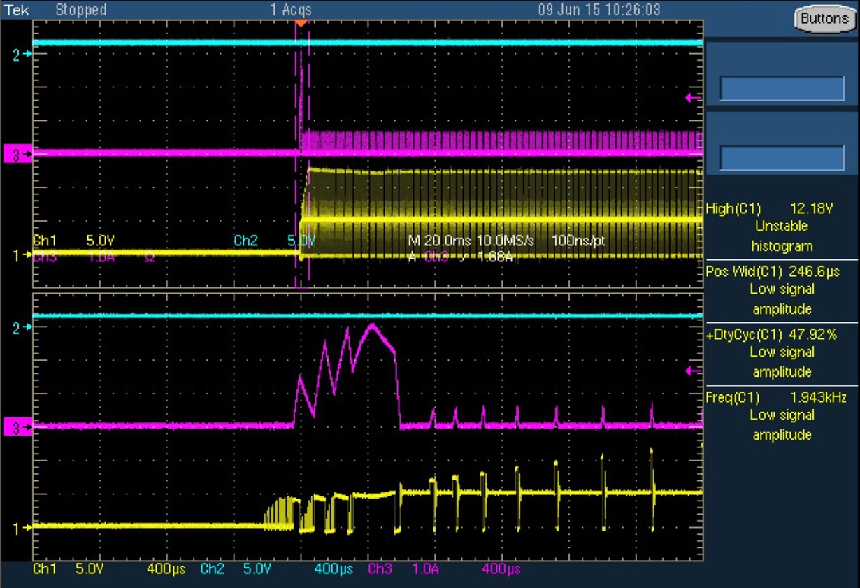
    In the attached scope screen dump you can see the inductor current (Purple), the voltage on D5 (Yellow) and the modem voltage (Blue) during normal

    12V input power up (without failure...).

    The current drawn during the modem power up is not by the modem it's by two 330uF tantalum capacitors on the modem module (they are needed to support the modem during transmitting bursts, they are a must!)

    I'm not sure anymore about the exact condition of first scope picture I sent, sorry, a long week...

    I'm not sure I understand the 9uS question.

    As a reference I add this scope picture of the board power-up it looks quite the same:

    Many thanks

    Omer Zeharhary

    AMI
  • Hello Omer,

    No issues! These waveforms will do.

    The 9us is the off time you will see in the SW node (CH1) when the part gets current limited. In the first waveform, you should see that in the CH1 waveform when CH3 waveform is current limited. The region where you have zoomed in.

    With the schematic we have here, the part can see a current limit anywhere between 0.76A-2.5A (avg.) based on the variations in ICL_ADJ in the part, Rds,on of the P-FET and the Radj used.

    From the first waveform (the one which you have labelled as NO failure) at 12Vin, the inductor current seems to be close to 3.5A (avg CURRENT limited) during the loading. The inductor which you had sent me the link for has 1.2A as sat current rating. I will check for the inductor again given the stress it sees when the circuit is loading up (3.5A for ~400us). You should try an inductor with higher sat current rating (preferably above 3.5A) and a sync-diode with higher forward current rating (at least more than 2A) as well .

    Is the second waveform from the same board and at 12Vin or is from another board at different Vin (24V?) Why don't you have any SW node waveform before the loading?  It is possible the inductor is not able to hold up at higher Vin when the part is loaded.

    Can you share one of your problem boards with us if it is permissible? We can try by having a look at the board in in our lab here.

    Regards,

    Sourav

  • Sourav Hi!

    I understand you answer and I'm looking for a better inductor (that will fit the board) to replace the one I currently using.

    I'll also ask my bosses if I could send you one of the boards that failed.

    What I don't understand is why the did the LM3485 failed, even when the inductor is in over current (and stop to function as an inductor) the current do not flow thru

    the IC!

    Can I just 'play' with the Radj value to solve this problem? I'll lower the over current cut-off so, it will increase the capacitor charge time a little and save the day...

    Many Thanks

    Omer Zeharhary

    AMI

  • Hello Omer,

    Could you please clarify your question?

    You can try reducing the Radj resistor which should pull down the CL threshold and limit the inductor current.

    Regards,

    Sourav

  • Sourav Hi!

    My question is since the LM3485 provide only the control signal to the PFET and read the output voltage it is not suppose to 'burn'
    when one of the power elements does not function right (or pushed beyond its limits...) so, what reason it have to fail, it's not in the high current path!

    Many thanks
    Omer Zeharhary
    AMI
  • Hello Omer,

    I understand the concern. However, when you have mentioned before about a 'failed' part, I was under the impression from your previous posts, that the part was either refusing to start up at 24Vin or starting and stopping out of regulated output voltage but in all the cases the part would still operate with input voltage reduced to 12Vin or until 22Vin functionally. In other words, the part would still work at lower Vin range.
    I am not sure if we have discussed about complete dead parts before or about parts which will refuse operate at any Vin. That would of definite concern.

    Please send me few of the dead parts when you get a chance. I can try them out in our lab in over eval boards here.

    Regards,
    Sourav
  • Sourav Hi!

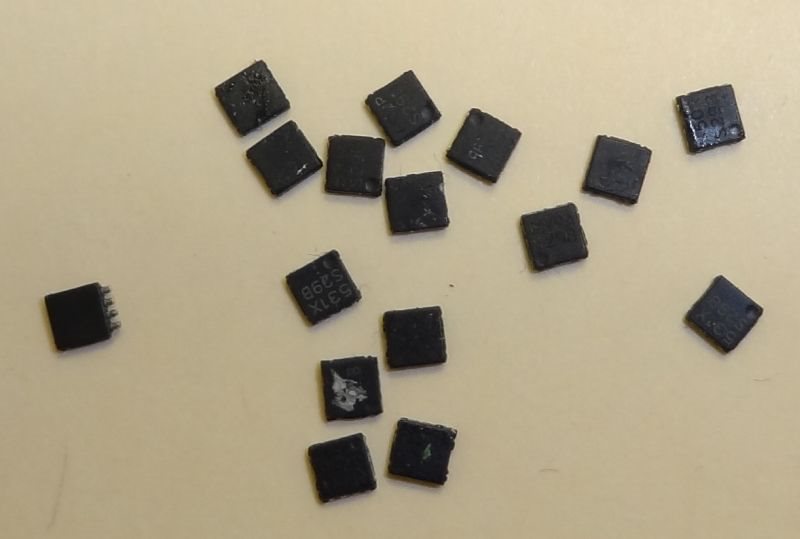
    If I wasn't clear, I'm sorry. When a part fail it's for good (bad...), as for testing the failed part, see attached picture:

    And that's not even all of them... there just no civilized way of taking the MSO-8 of the board.

    However I did made some progress, I lowered the Radj resistor to ~16.6K and now the board do wake up and run fine.

    What I get with the lower Radj is a stuttering start, it take the power supply 3 attempts to get the modem to it's right voltage, as you can see in the scope picture

    again, Blue modem voltage, Purple Inductor current and Yellow D5 voltage.

    I still need a more beefy inductor but, I think lowering the current limit is the way to go on this.

    Many Thanks

    Omer Zeharhary

    AMI

  • Sourav Hi!

    After more tests, the problem remains, the PS just can't handle the power-up current on 24V.

    I tried lowering the current limit, I tried better inductors but I still don't have a solid solution.

    I do have few damaged LM3485 chips that I, very carefully, removed from the board. If you want to test them yourself, I'll be happy to send them to you.

    Many Thanks

    Omer Zeharhary

    AMI

  • Hello Omer,

    The main culprit seems to be the inrush current due to the tantalum capacitors at the load end as you had specified earlier.

    Did you try replacing the FET and the Diode as well with higher current and voltage ratings? When the part get damaged, due you see any impact in the FET or the diode too? 

    One more thing along with reducing the Radj as specified earlier, it would be prudent to try a larger Cadj capacitor (like 4.7nF/10nF) as that should give you a soft-start during the powering up process.

    Regards,

    Sourav

  • Sourav Hi!

    Sorry for the delay.

    I did tried to replace the Diode with a 2A diode and the MOSFET to a lower gate capacity type, both without any improvement of performance.

    Moreover these components do function very well on other boards.

    Changing the Cadj value didn't help too.

    I would like to take advantage of your offer (if it still possible) of sending you the board ( and few damaged IC) so you could test it on your own.

    Many Thanks

    Omer Zeharhary

    AMI

  • Hello Omer,

    I had expected increasing the Cadj should really help you during the start-up.
    Just to summarize, I understand you present problem is the part is refusing to start-up at 24V and blows up. For all other Vins it is no longer an issue. Can you please confirm this for me?
    Can you please try these final combinations:
    1. Try Radj=30K and Cadj=47nF.
    2. Also, could you remove the connection between ISENSE pin and the cathode of the diode and add a 270 ohm resistor between ISENSE pin and the drain of the PFET.
    If both these options fail as well, we can look for a different corrective action.

    Regards,
    Sourav