This thread has been locked.

If you have a related question, please click the "Ask a related question" button in the top right corner. The newly created question will be automatically linked to this question.

TPS62120 inverting configuration - won't start under certain conditions

Other Parts Discussed in Thread: TPS62120

Hello,

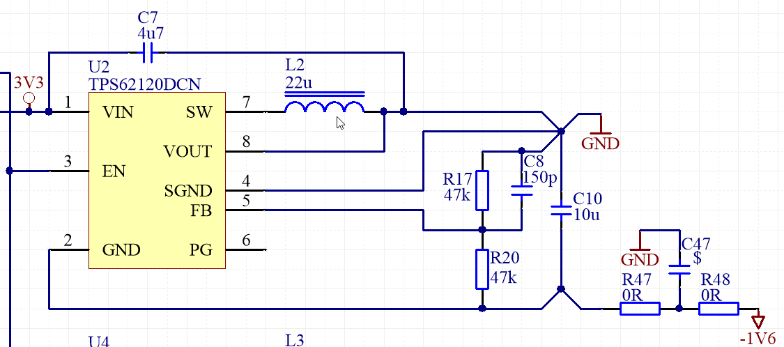
I'm developing a device which uses the TPS62120 to generate a -1.6V supply rail for operational amplifiers. The performance in terms of efficiency, noise, regulation and so on is entirely satisfactory, but the circuit will not start up under certain conditions.

We have tested the converter with either the EN connected to VIN or the EN connected through a level shifting circuit as described in SLVS478B, pargraph 2.1 and under certain loads the converter will not start up.

I have tracked the issue down to the fact, that there is slight leakage from the 3.3V rail to the -1.6V rail, which produces about 12mV of positive voltage across the converter output capacitor, which clearly holds the converter from starting up. As soon as the output capacitor is shorted (for example with a tweezer) the converter starts up and works reliably. My colleague also found, that introducing noise into the circuit via a loop of wire carrying a ~20kHz sine wave will also prevent it from starting.

So far we have been unable to find a solution that would work in all conditions and be robust against EMI, which may force us to seek other alternatives and we'd like to avoid this because we already have the TPS62120s in the circuit generating other power supply rails, and it would be convenient to reduce component variety on the PCB.

Please see below the circuit we are using.

  • Is the leakage maybe from the positive rail of the op amp? When you say 12 mV, is this 12mV from GND to -1.6V or from -1.6V to GND? i.e. which one is positive?

    Could you post a waveform of Vin, SW, and -1.6V when it does not start? Just tie EN to Vin.

    If it is due to leakage somewhere, lowering the FB resistor impedance to sink the leakage is likely a robust solution. This will help with the EMI sensitivity as well.
  • Tying the EN to VIN makes the covnerter start right now, but previously it was wired exactly in this way and it did not start. Connecting the EN to PGOOD from 3V3 converter solved the problem, until recently, when it no longer starts.

    I have tried to replicate the fault out-of-the-circuit, by connecting various capacitances and resistances between GND, -1V6 and 3V3 but could not replicate the fault. It also seems that connecting or disconnecting the SGND pin from system ground does not make any difference.

    Right now our workaround is to connect a low-Rds n-mosfet (IRLML2505) across the output of the converter and short it briefly from the microcontroller, this simulates shorting the output of the converter with a tweezer, which seemed to work every time.

    Could you please clarify one more thing: when the converter starts up, the current flows into the VIN pin, but how does it flow out from the chip? It would seem that the current path is through the GND pin, then through output divider and output capacitor and into the GND rail, and in steady state, the cupply current flows from VIN to negative output rail, is that correct?

  • Ah, so not starting was a one time event or is it repeatable?

    The device operates like a buck converter, even in the inverting configuration. So, current flows out of SW to GND through the inductor.