This thread has been locked.

If you have a related question, please click the "Ask a related question" button in the top right corner. The newly created question will be automatically linked to this question.

TL497a Inverter Voltage Drop

Other Parts Discussed in Thread: TL497A, MC34063A

Hi,

I have a TL497A set up to convert +5V to -19.5V. The problem I am running into is that the output voltage drops to -14V or so when the load is greater than a few mA. I need to be able to supply ~20mA.  Any thoughts would be appreciated.

Thanks,

Andy


Values:

Current limiting resistor: 2 ohms

Resistor 1: 18.3 k-ohms

Resistor 2: 1.2 k-ohms

Inductor: 470uH

Timing capacitor: 270pF

  • That IC is almost 40 years old. Why are you not looking at something more modern?
  • Well, it is what I have. Can you suggest another component? I am still interested as to why this design isn't working as intended.

    Thanks,

    Andy
  • I was just making a comment. Usually we can support questions about current ICs. I am sure anyone who worked on TL497A is long since retired. Can you post your schematic and some waveforms that demonstrate your issue? Maybe we can make some suggestions.
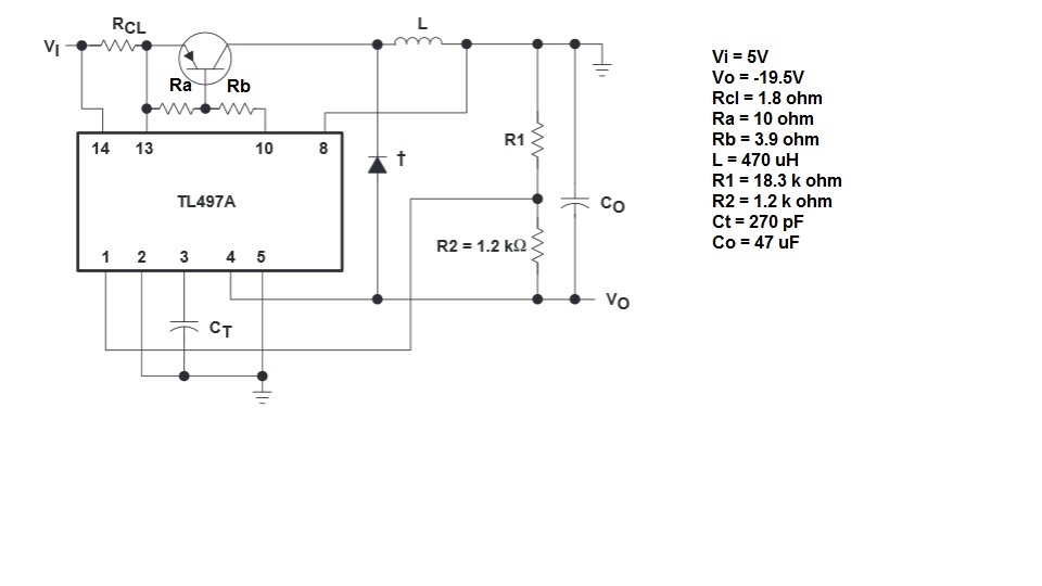
  • Below is the schematic for the inverting circuit that I am using  - it is taken from the data sheet. I calculated the component values using the equations in SLVA143 ("Designing Switching Voltage Regulators with TL497A"). I am using the extended power configuration to attempt to combat the issue that I am having. I have tried the standard configuration as well as other chips with similar results. I cannot provide a waveform for the problem, as I currently don't have access to an o-scope.

    I can provide more detail:

    The +5V is delivered by a simple linear regulator (LM7805) with bypass caps. Open circuit condition the circuit draws ~35mA and outputs -19.46V. When driving a 30 k-ohm load, the circuit outputs -19.45V at 640uA and draws 43mA. As the resistive load decreases the voltage increases - 10k: -19.43V; 5k: --19.29; 1k: -16.22; 100: -5.63. The fall off curve looks logarithmic. I am getting significant fall off in regulation when sourcing less than 4mA with conversion efficiency of less than 10%. Something has to be wrong here.  Thanks for your time.

    Andy

  • Perhaps, if I described the system in greater detail someone might suggest a better component than the TL497a. The power supply needs to supply +/-19.5V (at 25mA each) and +5V (at 250mA). It is designed to power a precision instrument that is battery powered (7.4V Li-ion battery), so efficiency and stability are important.
    Right now I have two TL497As producing the +/- 19.5V and an LM7805 for the +5V. The 7805 is just a place holder for the time being - I plan on replacing it with a buck converter. The TL497A for +19.5V is rock solid (though the efficiency is less than ideal ~65%).
    Thanks,

    Andy

  • Hello Andrew,

    We certainly have a number of devices that would be able to give higher efficiency in boosting to 19.5V, you may want to take a look at some of the devices in the following parametric search:
     http://www.ti.com/lsds/ti/power-management/step-up-boost-converter-products.page#p634max=20;75


     I have reached out to another contact to understand why you may be having the issues you are with the inverting converter and hope to get back to you soon.

    Best,
    Michael

  • Hello Andrew,

    Is it possible that you are seeing some issues due to layout?

    Best,
    Michael
  • Hi Michael,

    Thank you for the response. It is possible that layout could be a factor. I am not aware of any special considerations for TL497a layout. I am fairly new to SMPS design and would appreciate any guidance. Could capacitor ESR be a potential cause? At this point, I will likely have to move on to a different IC to keep the project moving forward, but I appreciate your efforts and would welcome any suggestions / possible solutions to this problem.

    Thanks,

    Andy

  • Hello Andrew,

    We have a number of app notes that give good guidelines and may help you with your layout. A couple of quick notes: placement of the active components as close to the regulator as possible is typically critical to the design.

    http://www.ti.com/lit/an/slyt614/slyt614.pdf

    http://www.ti.com.cn/cn/lit/an/snva021c/snva021c.pdf

    Another part you may want to consider as well is the MC34063A.

    Best,
    Michael