This thread has been locked.

If you have a related question, please click the "Ask a related question" button in the top right corner. The newly created question will be automatically linked to this question.

Questions about the TPS56221 overcurrent protection!

Other Parts Discussed in Thread: TPS56221, SWITCHERPRO

Dear all:

I have some questions about the TPS56221 overcurrent protection.

Our design is quite similar with the demo design of TPS56221, except the EN/SS and the ILIM pins.

Without the EN/SS capacitor and ILIM resistor, the TPS56221 will breakdown sometimes, and the relevant voltage before and after inductor is illustrated in Fig1.We measured the rush transient current during the startup which is almost 60A, and we are sure that is because of the large bulk capacitance (almost 5000uF), and the TPS56221 is self-protecting.

Although we know it will work properly with both EN/SS capacitor and ILIM resistor added, we cannot change the two current designs as follows, for some reason.

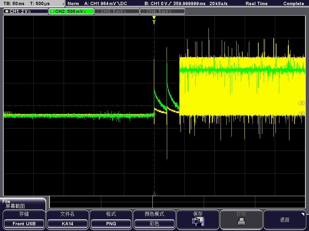
1) we add ILIM resistor 2.4K only, and leave the EN/SS pin floating.The current (pink) ,the voltage before and after inductor (yellow and green) are illustrated in Fig.2.

2) we add EN/SS capacitor 2.7nF only, and leave ILIM pin floating.The current (pink) ,the voltage before and after inductor (yellow and green) are illustrated in Fig.3.

Now both the two designs work properly, but are there any risks for the two designs? such as long-term reliability and safety? 

  • For 5000 uF output, 2.7 nF is too small for the SS cap. I would recommend 10 nF. You absolutely need to use both ILIM resistor and SS capacitor for reliable operation. Your fig. 3 is showing multiple over current during start up and both the input voltage and output voltage look unstable. can you post your actual schematic?
  • Dear John,

    Sorry for the late reply, thanks for your warmly answer. Actually, our design is quite similar with the demo design of TPS56221 in its datasheet, except the EN/SS , ILIM pins and the inductor.

    The inductor is 1.5uH, and we checked the loop compensation is well designed in the SwitcherPro.

    Now it's so urgently for us to know that,  if the abnormal design I mentioned  in my post is risky, and what will be the consequences?

  • It looks to me as if you have issues based on figure 3. Both the input and output voltages are fluctuating wildly. 1.5 uH is 5X more than the 320 nH in the example. I would definitely try a larger SS cap.
  • Dear Jonh,

    Sorry for the bad description in my original post, actually we used the SS capacitor 27nF(not 2.7nF), and the figures are the corresponding results. Need I try a larger SS cap?

    We tried to change the inductor to 560nH, and it seems not work to prevent the harsh current and the voltage fluctuations.

    So is there any risk for the design with only ILIM resistor(Fig 2 in the top post) or only 27nF SS cap (Fig 3 in the top post)?

  • None of those three figures look like acceptable start up in my opinion.