This thread has been locked.

If you have a related question, please click the "Ask a related question" button in the top right corner. The newly created question will be automatically linked to this question.

TPS55340 PROBLEM

Other Parts Discussed in Thread: TPS55340, TPS61175EVM-326

HI

I  AM USING THE TPS55340 IN ORDER TO BOOST VOLTAGE FROM 12V TO 14 VOLTS

THE PROBLEM IS THAT THE CIRCUIT DOESNT HOLD THE  LOAD CURRENT .

THE CIRCUIT ACCORDING TO THE CALCTOOL SHOULD GIVE  A 2.5 AMP THE

LOAD ACTUALY IS 1.9 AMPS,AND AFTER   2 MINUTES THE DC/DC STOP WORKING.

I ATACHED THE SCHEM DIAGRAM THAT I AM USING.

REMARK - WHEN THE LOAD IS LOW (0.7AMP) THE OUTPUT WAVE FORM AFTER THE

RECTIFIER DIODE IS STEADY AND THERE IS NO PROBLEM

 .WHEN THE LOAD IS HIGH(1.8AMP) THE OUTPUT  WAVE SEAM TO

BE  NOT STABILYS. AND THERE ARE A BLIMP AT THE OUTPUT VOLTAGE

AND AFTER 2 MINUTES THE DC/DC SHUTS DOWNTPS55340 _ DC_DC.pdf

THE VALUS THAT I AM USING ARE -

L - 3.3UHY

CSS-4.7UF

R FREQ -78.7K

R COM-1K

C COMP - 33NF

CIN - 15UF

CAN YOU ADVISE A SOLUTION TO THE PROBLEM?

THANK U

  • Can you post your waveforms?  Be sure to include the SW node.

  • hi john

    thank you fir your answer

    some background data abaut the circuit

    the circuit operates a small commpersor that use about 1 amp.

    the compersor works on pwm mode at 1 khz  .

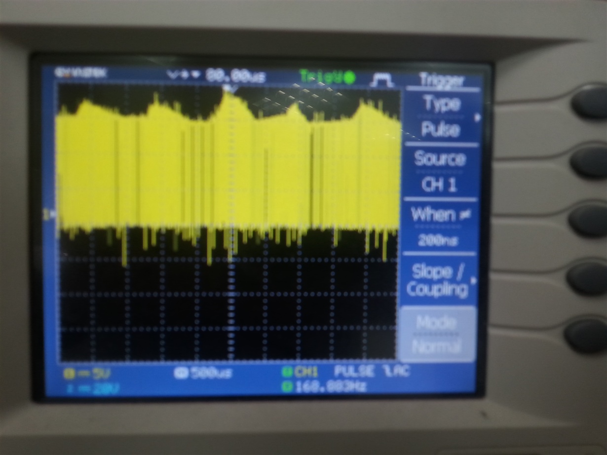
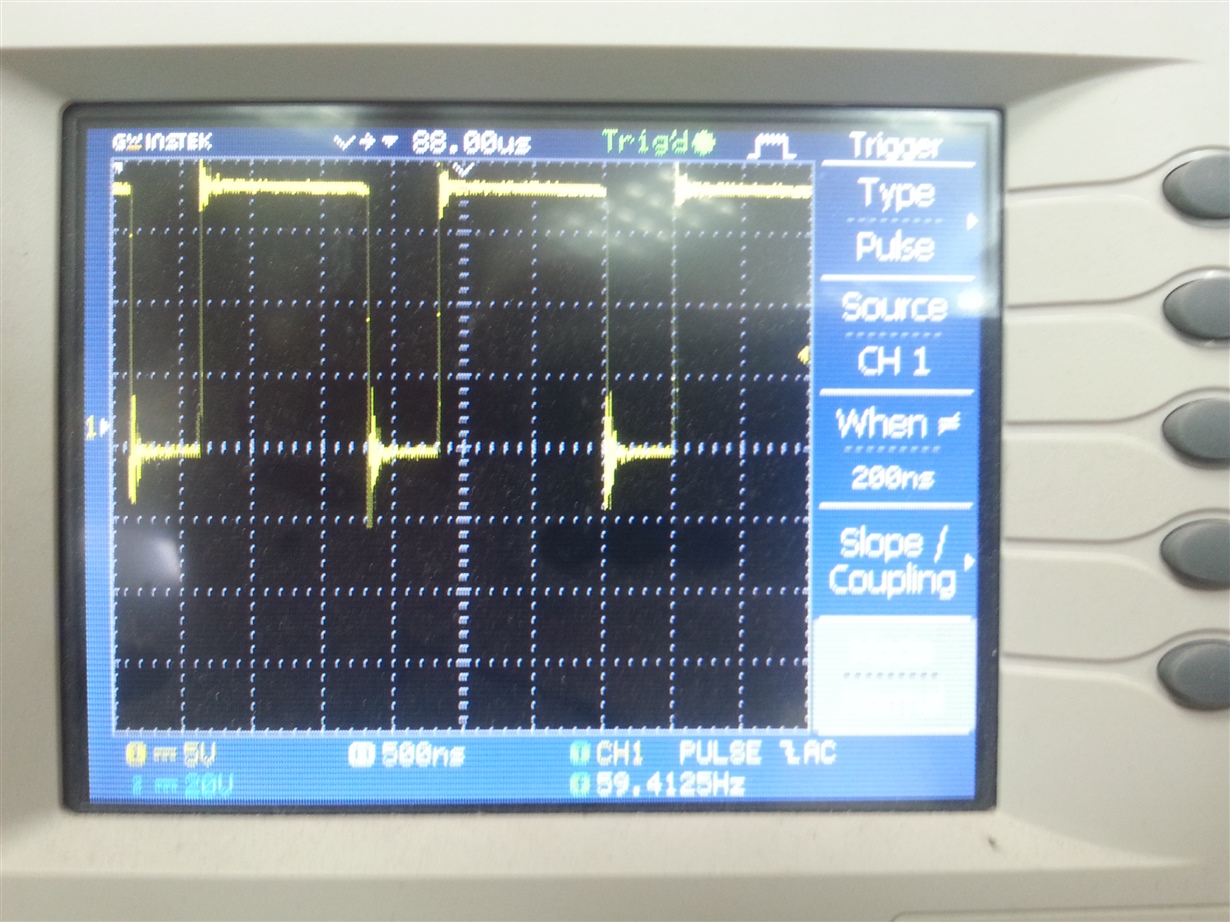
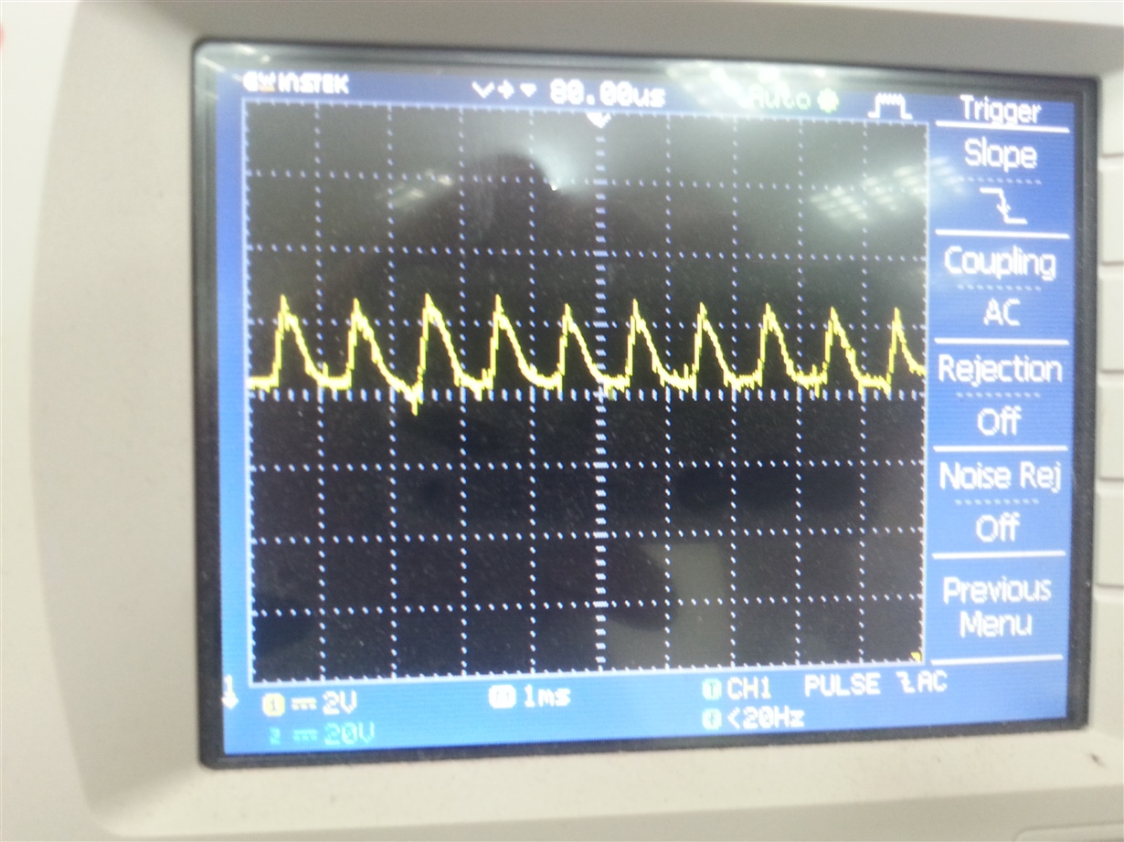
    a am ataching  few picture. 2 pictures of the output of the switch and one is the ripple at dc output of the dc/dc.

    as you can see the freq. of the "blimps" at the sw. are the same freq. of the  commpersor freq.

    the level of the ripple is about 2.5 vpp

    a atached also the data sheet of the coil 3.3uh that i am using.

    the problem is that i cant get the 2.5 amp from the dc/dc.

    the maximum current was 1.7 amp.   ihlp2020cz01-101738.pdf

    asher

  • It is possible that your input voltage supply is current limited, since the SW node peak voltage (VIN) ahs a large amount of ripple as well.
  • HI JOHN SORRY FOR THE DELAYED  ANSWER

    ANSWER TO YOUR Q   THE POWER SUPPLY THAT I AM USING IS LABRATORY P.S THAT CAPABLE OF

    SUPPLYING 10A. IT SEEMS THAT IT IS NOT THE PROBLEM.

    DOES THE VALUES OF THE COIL AND THE OTHER COMPONENTS SUIT TO CURRENT DEMAND(2.5A)?

    MAYBE THERE IS ANEED TO CHANG ONE OF THE COMPONENT BECOUSE THE LOAD CHANGES

     IS 1A  WHEN THE LOAD IS WORKING.

    IT ALSO HAS A HIGH  RIPPLE 2.5VPP. IS THIS RIPPLE OK IT SEEM  TO ME HIGH RIPPLE/

    HOW CAN I REDUCE THE RIPPLE?

    ANOTHER Q IF I NEED TO SUPPLY TO THE LOAD 2.5A  DOES P.S  OF 3A  CAN BE USED?

    OR SHELL I NEED A P.S STRONGER THEN 3A?

    REMARK- I AM USING THE DC OUTPUT OF THE DC/DC ALSO TO CHARGE A LIPO BATTERY

    THAT WORK AT 1.6 MHZ.

  • I would probably attempt to get the converter circuit working with out the compressor. The component values seem reasonable enough and the inductor has a high enough current rating. 3.3 uH is recommended for 2 A load, you can go a little lower for higher load current. You should be able to get 3 A from TPS553340. I bet it is something about that compressor. There is no doubt your input voltage is collapsing based on your SW node waveform. Try removing the compressor and use a resistor load. If that works then we can look to see about the compressor. It may have instantaneous peak current much higher than you expect. You may need to increase your output capacitor and recomepnsate.
  • hi john

    i didnt mention this but i already replaced the compressor with a resistor  6 ohmes to see if the load type is making any differnce in the behaver of the dc/dc

    by i got the same results. i replaced the coil from 2.2uhy to 3.3 uhy becouse the  dc/dc failed after few seconds with a load of  1.5amp/

    i will try to increase the output capacitor  & try also to  check the input current maybe there is a high inrusc current that i didnt see.

    i will be happy if you have another idea how to solve this

  • Remember that is you change output filter components, you may need to modify the compensation as well.
  • hi john

    i didnt make any progress in this problem do you have any idea how get  more current from the dc/dc(2.5A)?

    maybe the dc/dc type  is not  suit  for linductive load ?

    can you send  the  excel tool with correct  parts  maybe  i   missed something  ? 

  • Hi Asher,

    I also took a look at your component values and they all seem reasonable. There are a couple more things to look at closer in your design. First the PCB layout is important and I am guessing this circuit was built on a custom board. The TPS61175EVM-326 could be referred to for layout with the PWP package. You could even try testing out your circuit on one of these EVMs to see if there is a layout issue. Second it is important to have a ceramic capacitor for good bypass of the critical switching loop. This loop is the one created by the low-side MOSFET (SW and PGND pins of IC), Schottky diode and output capacitor. It is important to use ceramic (X5R or better) because they provide the best high frequency bypass. I'm not sure for your schematic what the 15 uF capacitor actually is.

    Best Regards,
    Anthony