This thread has been locked.

If you have a related question, please click the "Ask a related question" button in the top right corner. The newly created question will be automatically linked to this question.

TPS54625 Voltage Drop

Other Parts Discussed in Thread: TPS54625

Hello Everyone, 

I used the webench to create a 12v to 3.3v output @3.5A using the TPS54625,  

When i power the supply up without any load, it outputs 3.34v, which is fine, but as soon as i put a load on it, it instantly drops to 1.9-2.0v, the load is about 2.4Amp at start up, 

I Copied the schematic 1:1 from the Webench, and the board layout is pretty much the same. I have done the same for 2 other voltages, 5v and 12v using 2 different products without any issue.  

The only thing i could see wrong after first powering it up was the no load voltage was about 2v with the resistors that webench and the datasheet suggested, so that might be a sign of a faulty IC?

Im really not sure whats wrong, This is my first project like this so i wouldn't be surprised if its my mistake somewhere, ive spent the last 5-6hours re-reading and re-checking everything and it all looks good. The PCB has no faults, the values of caps and resistors are all correct and the 12vin is stable.

Any help would be greatly appreciated. 

  • Check VFB.  It should be 0.765 V.  With load the SW waveform should be a rectangular pulse waveform.  You can post your waveforms here.

  • Hi John, 

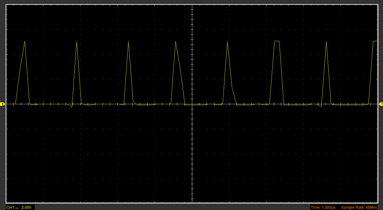
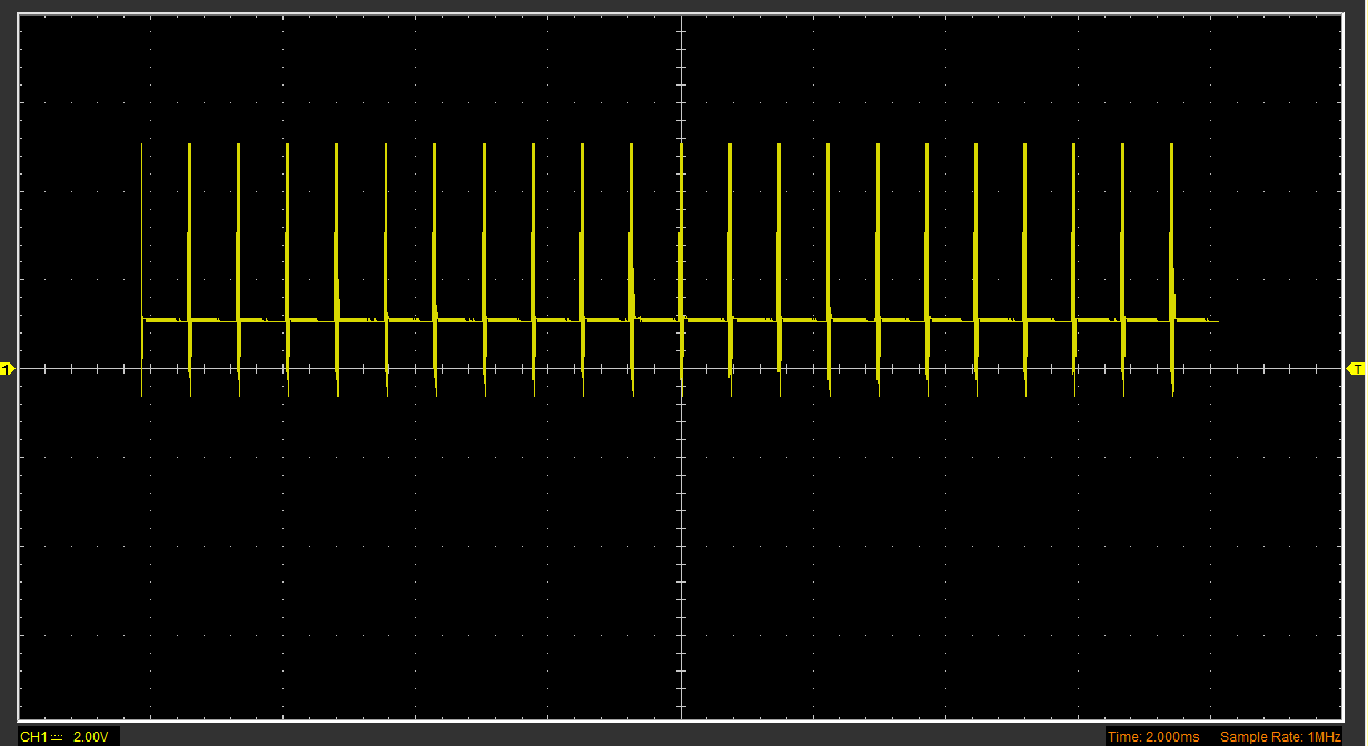
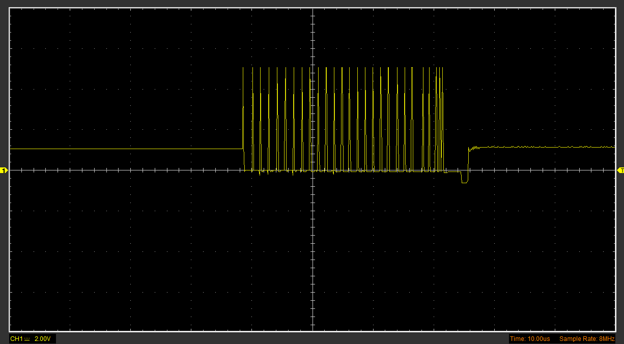
    Sorry for the delay,  I have attached captures of the signal below... doesn't look good to me. Although i am getting 0.775V on VFB.

    Chris

  • Yes that does not look correct. SW should switch from ~0 V to 12 V. Can you post your schematic and layout? how many prototypes show this behavior? If it is only one, try replacing the IC.
  • Hi,

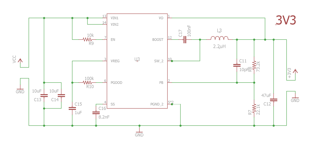
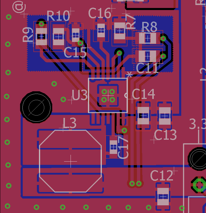
    I have attached the schematic and section of board layout, There are some mistake that i have fixed with bodge wires, and once this issue is figured out, they will be implemented in the new board revision, Noticeably, the lack of connection to PGND pins 8 & 9, and that only one of the SW pins is connected.

    This is the first batch of boards, and been tested on 2 different ones with 3 different IC's, Like i said in my first post, the first board output 2v without load and not 3.3v, when the ic was changed, it was outputting 3.3v, still with the voltage drop under load.

    Thank you for your help on this, Its very much appreciated

    Chris

  • The circuit will not work properly with PGND not connected. You can probably connect the two SW pins directly. You will need to provide a very solid low impedance connection to PGND. When you spin your PCB, I would take a look at the EVM layout for guidance.
  • Is the problem with the voltage drop because of the PGND not being connected on the board?, I have connected them to GND by scraping some of the mask off and soldering them with thick short wire, is that not sufficiant enough for temporary use? because it has not changed the voltage drop issue.

    John,

    First of all, i just want to say thank you for your help, I really appreciate,

    Second, i wasn't to apologies for an apparent waste of your time, because i just checked and the connection from PGND to the rest of the board was really bad, even though i had redone it several times. I just made up a new board, with a solder bridge in place to join PGND and GND together and its working flawlessly from what i can tell.