This thread has been locked.

If you have a related question, please click the "Ask a related question" button in the top right corner. The newly created question will be automatically linked to this question.

TPS63000 Quiescent current

Other Parts Discussed in Thread: TPS63000, TPS63000-Q1

Hello,

We use the TPS63000DRCT in our design (low power device) as a power supply.

Now for us, the quiescent current is very important (we use the low power save mode, pin #7 pulled low)

Our product is consuming only 30 uA in sleep mode, and the quiescent current of the TPS is less than 50 uA. So We expected a total current draw of approx 80 uA. This is verified during design, and is OK (85 uA).

But it seems that units that are produced from some batches of TPS63000 draws much more.

I measured 200 uA yesterday. So I replaced the TPS with one from the previous batch, and the current was OK again.

The one with the low quiescent current (correct) has this code: 5BI CCCT. The other one (44WZ354) has a much higher quiescent current (200 uA).

This one I replaced for a new one: (5CI ART7) and has also a much better quiescent current (old IC 200 uA, now 115 uA).

I mentioned on the reel was noted "Revision C".

Now I like to know the differences between the Revisions, because I cannot find them in the datasheet.

Can someone explain the differences I measure between the different batches of IC's? I also buyed a batch of TPS63000-Q1 (automotive) They have also the high quiescent current. These ones have the batch code: 43K DOC 7


Regards Remco

  • The quiescent current is a datasheet parameter, it is expected to be the same for all the batches.
    Could you solder one unit of each of these batches on the TPS63000EVM and measure the quiescent current?
  • Hello,

    I soldered the different units on the TPS63000EVM and all looked good at first.

    But when I load the board with a capacitor (1000uF) I can see differences.

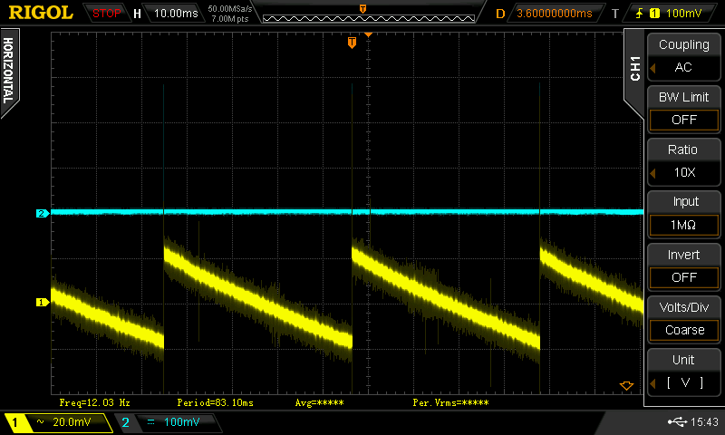
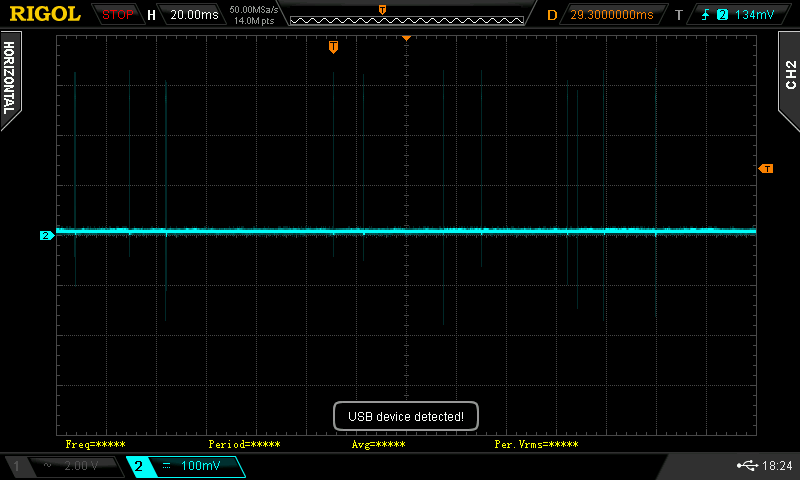
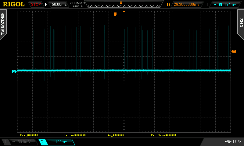
    With the automotive version of TPS63000 on the board, the quiescent current is 50uA (normal) and the riplle has a period time of approx 40 mSec.

    The signal on the coil is synchronized to this period time.

    (see picture, the blue peaks are hard to see, but they are there, nicely synchronized)

    When I load the board with a capacitor, the unit draws much more , like 180 uA current. and I can see that the ripple is gone, and the buck is no longer synchronized. It it switching faster.. That's why the quiescentcurrent gets higher I think.

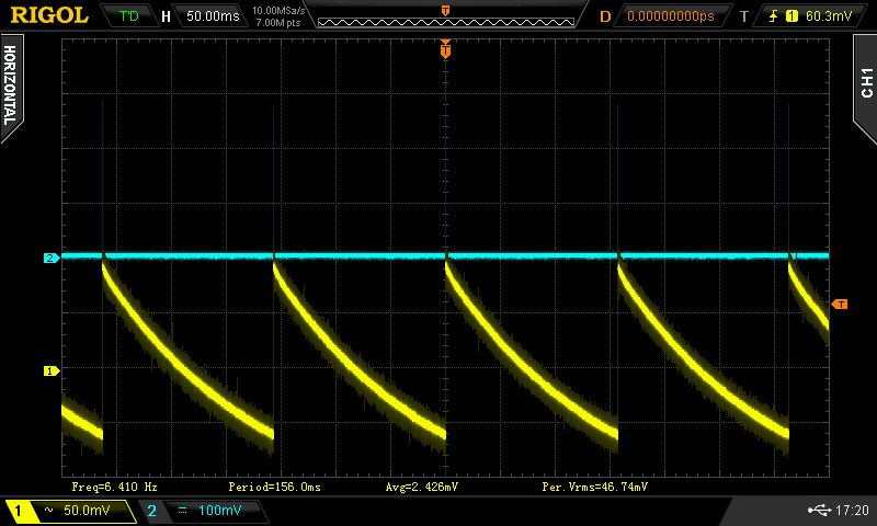
    Then I replaced the unit for a rev c unit. I noticed also 50 uA quiecsent current, but the frequency of the ripple is much lower! see photo. (the period is now like 150 ms. 

    When I load it with the same capacitor, the quiescent current increases a little, like <10uA. so a big difference!

    Also the signal on the coil is not so "busy" like the other unit.

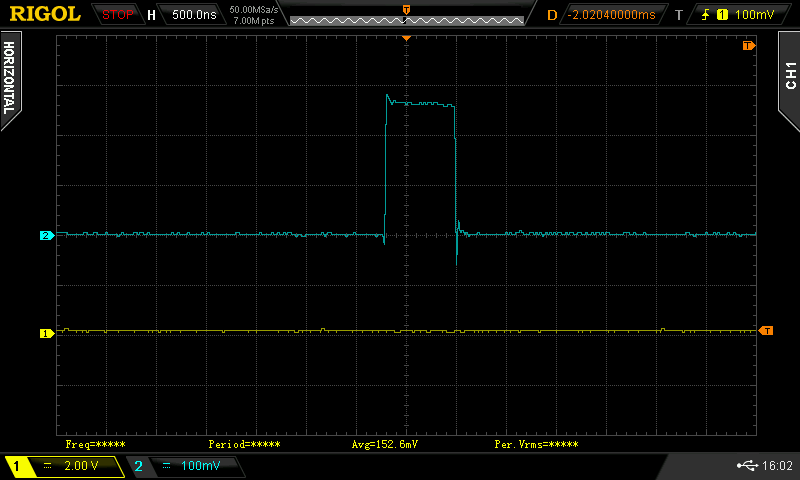
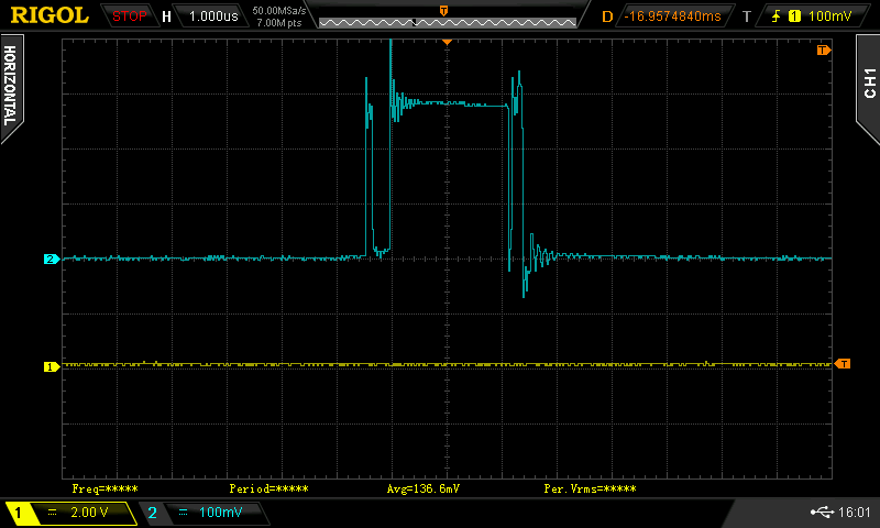
    Also I mentioned, when I zoom into this coil signal, there are differences between the 2 units.

    unit automotive: 1 single puls (see photo)

    unit rev: c: multiple pulse.

    So, I noticed a few differences between the two units (frequency of ripple during quiecsent, and the pulse on the coil)

    On my board I see the same behaviour.

    Now, the Rev: C unit is behaving much better in my application, because I have a lot of capacitance on the board , and I need a low quiecsent current.

    Can you advise me what to do? Do you know all the differences between the revisions?

    Regards Remco

  • Hello, Also I replaced the unit on my own board for a revision C unit. The sleepcurrent went down from 199uA to 80 uA.

    Also you can see there is less activity on the coil , with the rev C unit.

    I am very curious to the differences between the revisions. What can I do to lower the quiecsent current of my design?

    Here you see the rev: C version

    And here the other unit

  • Just to double check did you measure the quiescent current as described in this app note?
    www.ti.com/.../slyt412.pdf