Hello, I am using the TPS61088 to convert a single cell lipo battery voltage to 5V @ approx. 2A. In my testing, I have a 1.16A resistive load.
In no load conditions, the output is 5V. This is good.
When i connect my load, the output drops to ~3V and the waveform is a sawtooth (approx 1.3V pk/pk). The yellow waveform is the "5V" output AC coupled. The blue scope is not relevant (it's the 3.3V rail).
This circuit was designed with the webbench wizard. Here it is:
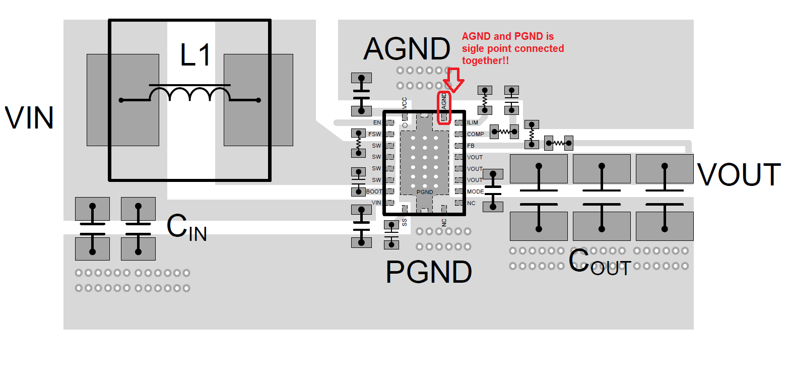
The layout isn't terrible
The inductor is rated for 7A, current limit set to be between 4-5A and the parts aren't getting warm as far as I can tell.
Probing the SW pins (4-7) reveals the following waveform:
zoomed out (yellow "5V" rail and blue is the SW pins)
It looks like the IC stops switching when SW reaches ~5.25V.
I don't suppose the device is hitting a current limit.
I suspect there isn't enough output capacitance and/or there's something wrong with my compensation network values.
Before making this post I increased the input capacitance to 44uF and output capacitance to 88uF. This didn't fix the issue but it made some changes to the circuit's behavior:
The sawtooth frequency dropped to ~2.8kHz and it's a cleaner waveform
The average sawtooth voltage increased to approximately 3.6V
Last, one thing that I tried now that I didn't try before is I increased the input voltage from 3.4V to 4V. When I reached 3.9V the sawtooth went away and it was a pretty clean 5V output supplying 1.7A to my load, and the SW pin was a clean square wave running at about 50% DC.
My question is: Why does the boost circuit not work when the input voltage is below 3.9V? Could this have something to do with the internal current peak limit set by the internal error amplifier, and the logic turning off the switching FET too soon?
Any help is appreciated. Thanks
Edit: I experimented with different values for the compensation network but the changes I was making didn't make a very noticeable difference. I probed COMP pin and noticed that the signal would periodically drop to 0V momentarily before shooting back up to a nominal 1.7V. Looking at the block diagram, the only component that could pull the COMP node to ground would be the error amplifier. The inputs to the error amplifier is soft start and the feedback pins. I don't think the soft start circuitry is affecting anything and the feedback node never reaches 1.2V, so I doubt it's responsible for pulling COMP node to 0V. Any thoughts on what else could make this node drop to 0V?
Edit: I reduced the load to 0.8A and I'm getting a very well behaved circuit when Vin = 3.2V - 4.2V. The sawtooth comes back when lower the input voltage below 3.2V. Again, this makes me think the problem is the device is hitting some internal current limit and the part's deadtime before restarting the switching cycle is too long. I'm looking into this now.
Edit: Curious what would happen... I increased the Ilim resistor to allow for 11A of current. I think this made the circuit worse... On the other hand, I decreased the current limit to 6.3A and it also didn't help or change much.
Edit: here is a scope capture of the output (yellow waveform) and the COMP node (blue). Notice how something is pulling this low (I still assume it's the error amplifier doing this, but why?)
Edit: I tried increasing the capacitance of the RC filter on the COMP pin from 1.2nF up to 14nF and there was no difference in behavior. I also tried an RC combination of 6K and 4.7nF and there was no difference in behavior.


