This thread has been locked.

If you have a related question, please click the "Ask a related question" button in the top right corner. The newly created question will be automatically linked to this question.

TPS62125 in Inverting Buck-Boost Configuration, need help with Tina simulation.

Other Parts Discussed in Thread: TPS62125, TPS62135, TPS63700

Hello,

I am searching for a low power solution to generate -12V for an analog switch. The load current is minimal <1uA at -12V.  The input is made of two series connected AA battery. To work on the concept I am using the TPS62125 in Tina, note that the input range of this IC is 3 to 17V, the minimum input voltage is higher than the typical working input voltage for my application.  I'd appreciate if someone could advise for a better fit.

The issue I'd like to get some understanding on is the following simulation results in Tina with the TPS62125 transient model.  This behaviors is consistent in Webbench.

In this simulation, The input voltage is 4V, I am expecting an output voltage regulated at - (1 + 2Meg / 1Meg) x 0.8 = -2.4V. as you can see from the waveform at the output node of this inverting topology, the voltage keeps ramping down more and more negatively, and does not regulate at -2.4V.  I appreciate if someone could point out, what is going on.

Thanks

FI

  • BTW, even with this part, it may have a chance to work since Vin seen by the converter is Vin - Vout, I am not sure whether there are more startup considerations, if the input voltage is say at 2.4V. Anyhow, would like to understand what is going on with the sim. Thanks.
  • Your figure didn't come through but I don't think it is necessary. In general, the inverting topology with a buck is not supported with the models.

    In any case, the maximum recommended output voltage for the TPS62125 is 10V. The new TPS62135 goes to 12V, but it won't start from 2x AA cells.

    Is there another voltage in your system?
  • Chris thanks for the reply.

    I do have other voltage rails I could tied into, 5v and +12 boosted from battery.  All running on ti parts for low Iq.  I initially wanted to be able gate this supply off separately, but there are options.

    Thanks for introducing the tps62135.  The  peak voltage I expect the FETs block off is -10 V,  marginal if the tps62125 is used. It comes down to how much margin I feel comfortable and static current drain +5uA, I guess there are better low hanging fruit to gain that back.  Do you happen to know another part that would out do on the two figures?  Thanks!

  • Yes, the 5V is easier to use to power an inverting IC. You could do 5Vin to -10Vout with the TPS62135. Or the TPS63700 allows you to go lower in output voltage if needed.
  • Chris,

    How's going? Want to check in and pick your brain again.

    We got a test board back, and are trying the inverting boost with tps62135.  The schematic is attached. 

    The inductor is Murata LQH3NP series 1uH part number LQH3NPN1R0NJ0L.

    Resistors are 0603 thin film. R1 = 5.64M and R2 = 350K, for a 2uF feedback current cost (accuracy is not critical).

    Output caps are parallel 0805 10uF with minimum 20V+ rating.

    Input cap is a standard 0603 X7R good for input voltage of 5V+

    Output PMOS discharge switch for shutdown is tied to Vin, so that it is off and not loading for this test.

    The output load is a 2K resistor to ground drawing a max of 6mA from output at  -12V

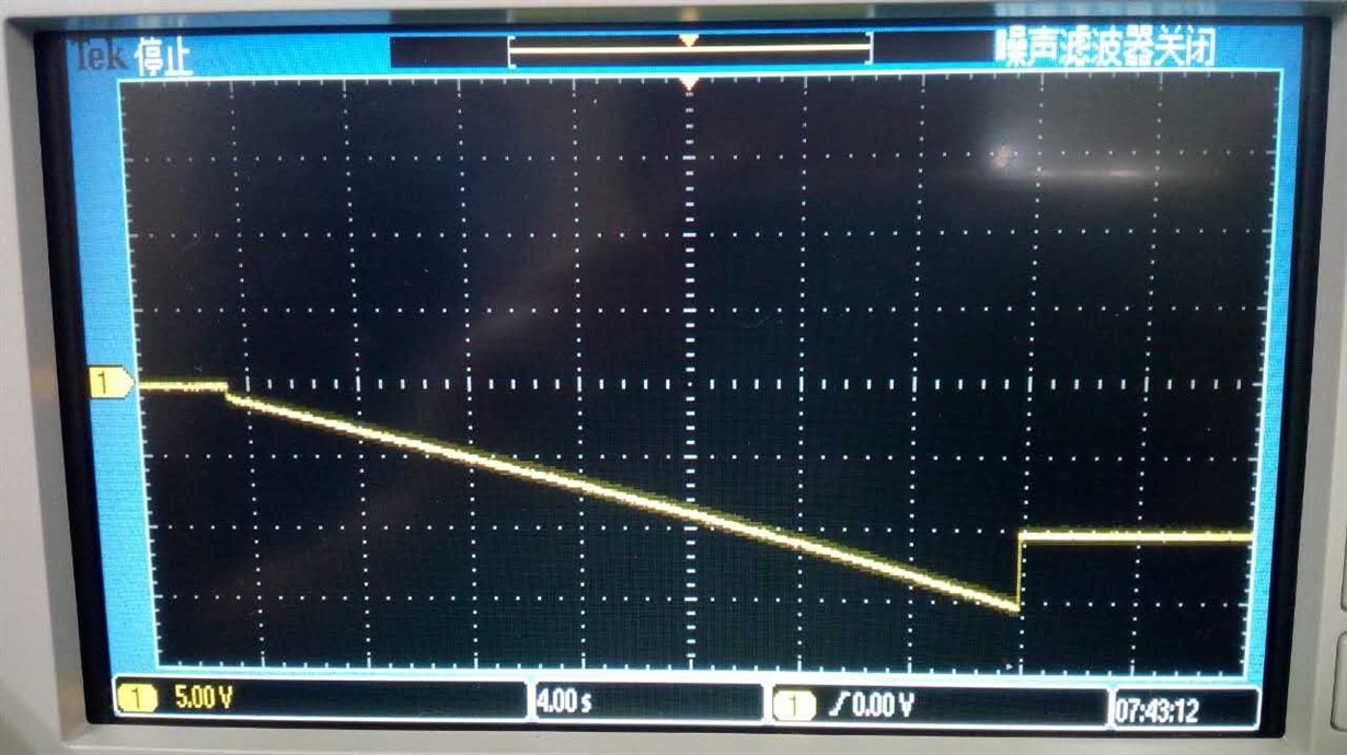
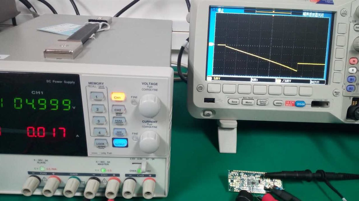
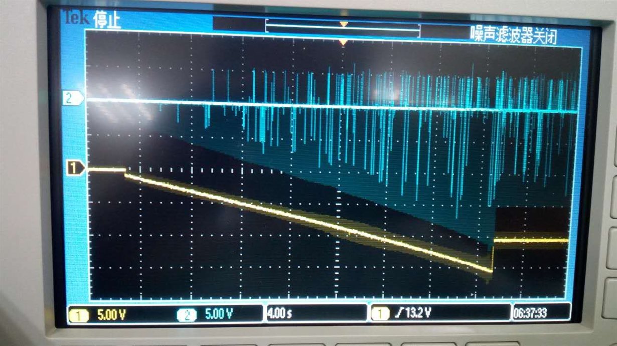
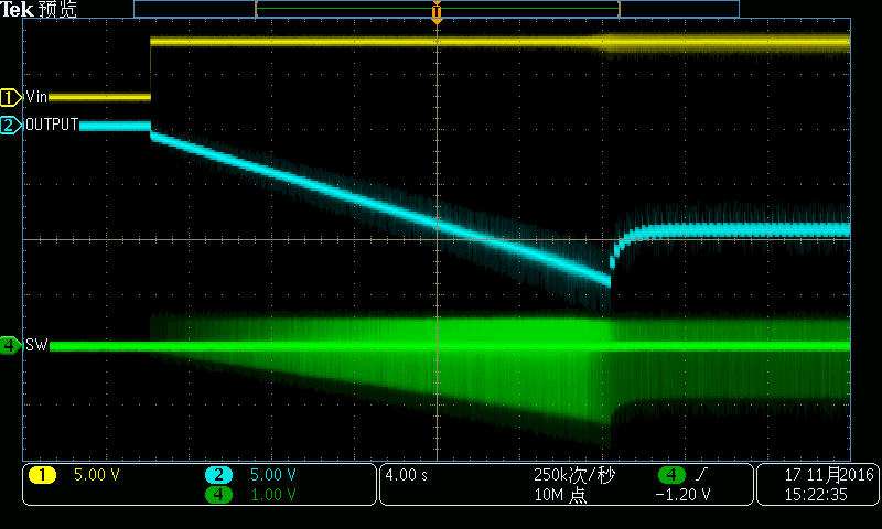
    The issue on immediate functionality is that, this circuit take 30 seconds to come up to a stable point (~-10V) and the end point transition has a significant overshot as shown in the attached waveform snapshot.

    The engineer tested this circuit used only 3V input supply, though the 3V is stable and low impedance from a power supply.

    Please share your thoughts.  Appreciated.

    Best

    FI

  • 3Vin is right at the minimum for the device to turn on, so I suggest increasing this and seeing if the behavior improves. If not, please post a waveform with your Vin (at 5V), Vout, and SW.
  • Will do, and followup on this post first thing tomorrow. Now, do you have a Spice model for this part that can be use, what is the expected startup time for this implementation? Thanks!
  • No, this model does not support the inverting configuration.

    SS time will be much faster than seconds. There is something not right here.
  • Hello Chris,

    Things did not improve, here are some observations:

    Testing the implementation at 5V input did not improve the outcome.  The photo shows the supply at input and output trace over about 30s.

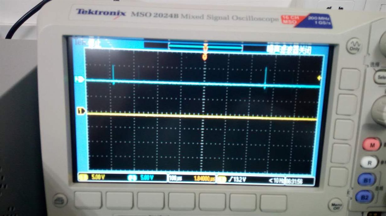
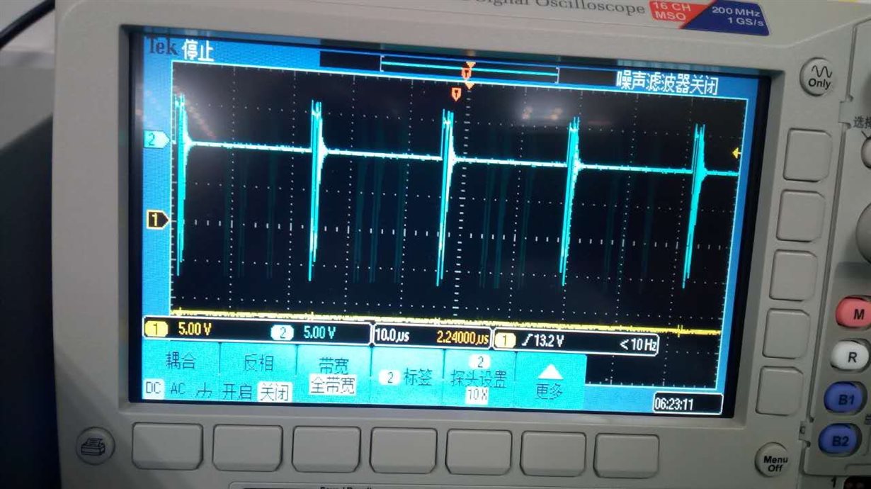
    The SW node waveform reveals long switching interval. The interval is longest at initial startup and becomes shorter and shorter as the output is coming up.

    The initial startup SW switching interval is shown here with a 1nF SS: ~680us

    The initial startup SW switching interval is shown here with a 10nF SS: ~410us

    In a steady state condition after startup, the switching interval becomes about 20us

    The input waveform is pretty stable driven by a power supply at 5V.  The average input current was at 17mA for a 2.2Kohm (~5mA) load at output at steady state. 

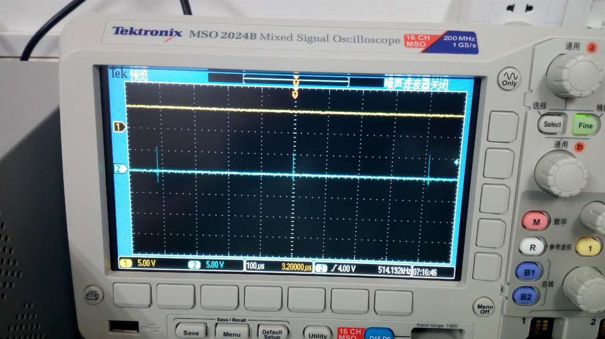
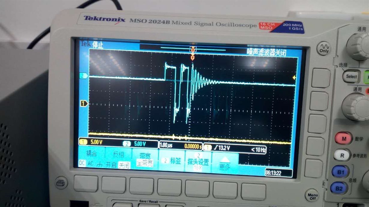
    In addition here is a zoom-in on a switching pulse at SW node.

    Please advise on what's maybe happening, we need to decide whether we need to change our design asap.

    Thanks

    FI

  • Hi,

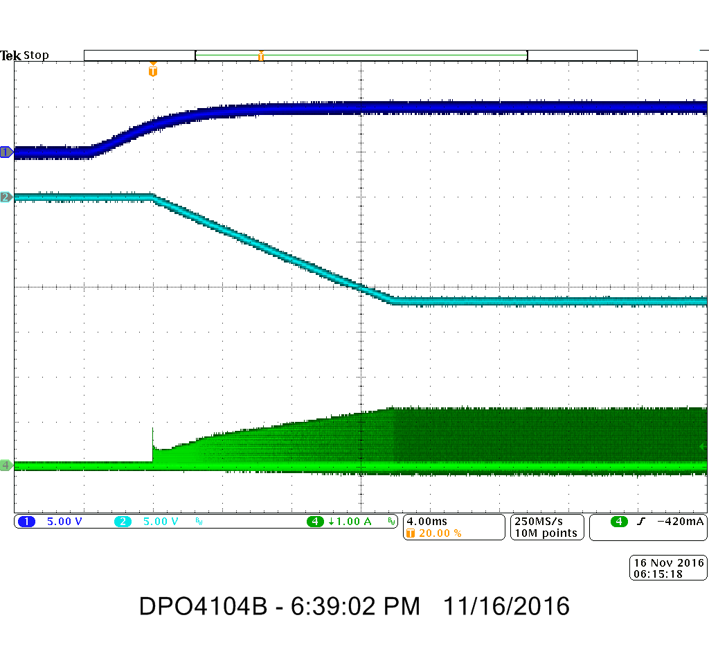
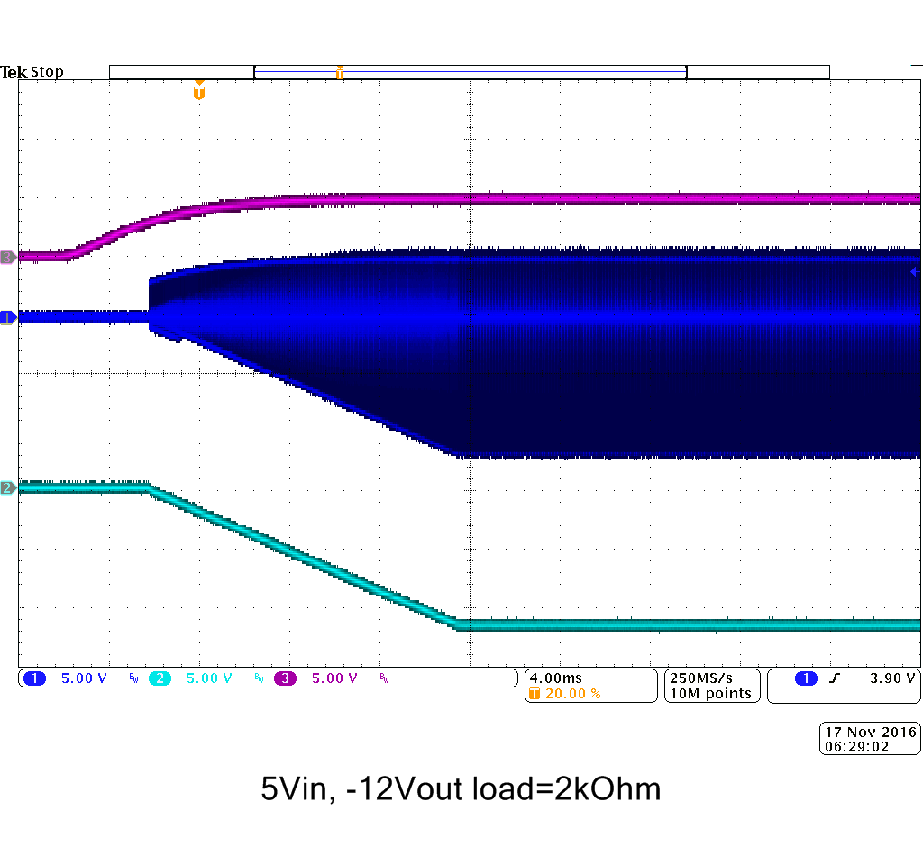
    i did a startup measurement on the TPS62135 with following conditions:

    Vin: 5V,

    Vout:-12V (same resistors as above)

    Load: 2k

    Cout: 22uF

    Cff: 50nF


    Blue: Vin, Light Blue: Vout   Green: Icoil

    With this conditions i couldn't see any issues. Could you generate the same plot?


    Thanks,

    Michael

  • Michael, your results are encouraging, thanks for the support. Your traces looks good and the part switches nicely. Just to make sure the comparison is strict.

    Can you confirm the connections in your test are exactly the same as the given schematic in the earlier post, MINUS the Cff (I assume it is Css for softstart)? And if Cff is for soft start, could you confirm with the SS pin open, 1nF and/or 10nF? Really appreciated. Also is your version of the IC the straight up tps62135 or the tps62135(1) version?

    Putting some expectation on this on going communication: The engineer who is hands-on with this block now is at his night time, I am designing and facilitating around the clock.

  • Michael will have to reply back tomorrow on the specific IC version he used, but otherwise his test setup matched yours. Yes, Cff should be Css. The 14 msec SS time is right where it should be for a 50 nF cap.

    To help speed this up, could you post a similar waveform will all traces on one scope waveform? And the PCB layout and BOM for the passives around the IC would be good to check as well.
  • Hello Chris,

    Here is what I have for now.  I will populate and update once I have better information

    Here is a waveform trace of the SW and output at comparable scale minus input for now.

    Again, here is the schematic

    Here are snapshots of the layout, dark green is ground

    Top Layer

    Inner Layer 1

    Inner Layer 2

    Bottom Layer

    Immediate BOM information

    Please let me know if you see something jump out. 

    FI

  • Thanks for sharing. What caps did you install on these PCBs that you are testing?

    You might try installing a SS cap of 10 nF or so. One of your previous posts said that you did this, but did it speed up the SS to a normal value?

    Could you try lower impedance FB resistors? i.e. 56.4k and 3.5k? This would help rule out any external noise influence.

    As well, look at Vin at the IC (on C26) during startup. That looks to be a narrow trace from elsewhere to this circuit, so there may be quite some voltage drop.
  • Sounds good, will followup. Just curious, how did Michael measure the inductor current?
  • Inductor current can be measured with a current probe around a wire which is added in series with the inductor. Remove the inductor from the PCB, solder its SW terminal back to the PCB with the other terminal in the air, then add the wire between Vout on the PCB and the other terminal of the inductor.

    It would be god to measure the inductor current if you have a current probe. This is very useful for debugging.
  • We don't have a current probe for the scope.  We can only obtain voltage trace right now. Let me know the best way to present this information.  The engineer still had no luck getting it to work as intended just now. He made another board with a 47nF CSS,mimicking Michael's test, the behavior is still the same taking 30s to come up.  He is assembling information per the above list, but in general, the caps are all rated at 25V X7R or X5Rs.  He did try lower value feedback resistors though yielding the same result.  The trace you pointed out is not long, pretty much ends at the edge of the capture, it should be 0.4mm if not any bigger, I can widen that in the coming revs, but the important thing is that, the test is done by soldering wire directly at the input cap.  Thanks again and let's figure this out.  Best.

    Our engineer would like to get a close up picture of Michaels setup just to compare and see anything is wrong with our board.  Thanks again.

  • Hello Chris and Michael,

    Made another board, same un-functional behavior, setup exactly like Michaels with a 47nF Css.  Engineer wants to have a close up on Michaels board.

    Here is the updated scope capture

    Here is the updated BOM

  • Hi,

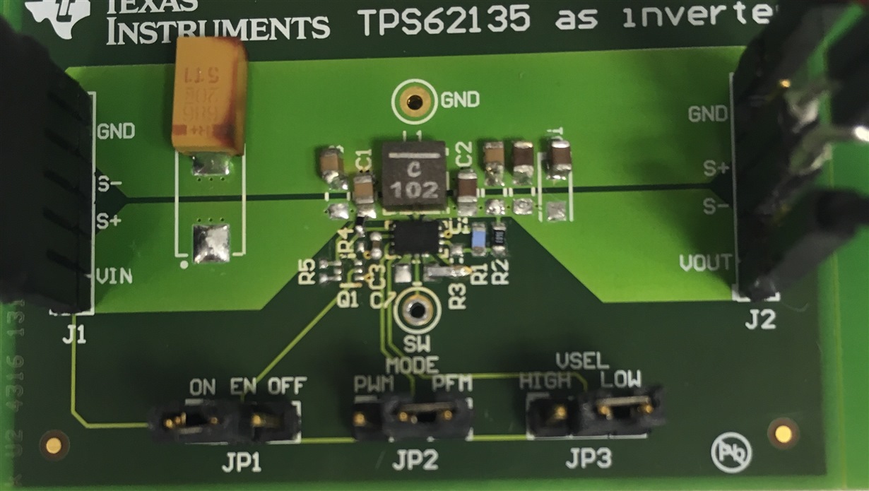
    below a picture of the board which i used for the measurement. 

    I tried to use same values and same connections as on your schematic. The device is starting as shown below.

    Which inductor do you use? on the schematic is a 1uH but on your BOM is a 2.2uH

    Regards,

    Michael

  • The current board has 2.2uH on it the Isat is a little over 1A, I wonder whether that has an issue.
  • Depending on the softstart time, the inductor current can get much higher during startup.
    I would recommend to use a 1uH with higher saturation current.

    Can you see this behavior on several boards with several IC's?

    Regards,
    Michael
  • Yes,

    We made two board, tried three ICs, the latest one has a softstart Css=47n. The behavior is the same. Why 1uH instead of 10uH, meaning why go smaller? I see the Coilcraft inductors (the one you use) are very good I am looking into the XFL series, they handle up to 5A, wow.
  • Any chance it is hitting the current limit? HICCUP?
  • From your waveforms, I don't think so. But you could zoom in on some switching pulses. If you see 512 of them in a row, this is hiccup current limit.

    It might be worth trying a higher saturation current inductor. Generally, in a given package size, saturation current goes up with reduced inductance. The 1 uH in your Murata family has a little bit higher Isat rating. If you are able, I would find a >3A Isat coil to test.

    Could you remove SW and add FB and SS to your last waveform?
  • Michael and Chris, Thanks for your support and input.

    I am going to pause this post for a week or two, as I requested the board to be send to me to have another pair of eyes and hands checking on it.

    Will followup in a week or two. Cheers and thanks.

    FI
  • Hello Micheal and Chris,

    Just want to close the loop, I have received, assembled and tested two boards, both are working fine.  Though I am trying to come up with better topologies for lower Iq and in-rush current, the inverting boost tps62135 per this design yields (120uA no load) and in rush current (> 1A).

    Again, thank you very much for you support!  Best!

    FI

  • Thanks for posting the resolution to your issue. Do you have an idea of what was wrong before?

    Using a SS capacitor should help with the inrush.

    Assuming your load is still very light, you might try a 2.2uH coil to try and improve the input current drawn.