This thread has been locked.

If you have a related question, please click the "Ask a related question" button in the top right corner. The newly created question will be automatically linked to this question.

TPS564201: Short Circuit Issue

Part Number: TPS564201

Hey,

I'm experiencing  quite strange behaviour while using the TPS564201.

I have designed a circuit very similar to the datasheet suggestions. Vin is 12V from a stabilized source. Vout is configured to 5V (I have a second configuration with 3.3V showing the same behaviour).

Cin is 22 µF with 35V max, Vout is 47 µF with 20 V max. C_boost is 100nF. The feedback resistors are 56kOhm and 10kOhm (should result in about 5 V). The inducance is 3.3µH as recommended.

I double checked the layout to be according to the design example in the datasheet.

When I applied a voltage (as mentioned 12V stabilized) to the input rail, I got a short circuit on the output side. I then varied output impedance, to rule out any open load stuff, which didn't change anything. I did a oscilloscope measurement on the output side and it turned out that the dc/dc controlls the output voltage to 5 V for a period of about 10ms and then goes to short circuit. I am wondering ehy it behaves like this, since it seems that everything is correct for a few milliseconds and when the output is stable, it goes to undefined behaviour. I checked the output and input for shorts and/or strange impedances but everything looked okay.

I hope you guys can give me some tips.

Thanks in advance!

  • Hi,

    From your description, SW pin should have been short to GND, rignt?

    Alll boards have the same issue? Did you rework for a new IC for double check?

    Please upload you schematic and layout for review.

    BR,

    Yuchang

  • Hi,


    neither V_out nor SW are shorted in disconnected state, it appears to be an internal short. The symptom is high current draw on V_in and voltage drop to unter 1 V. I have the same issue for 3.3V on the same board, exactly the same schematic and layout, only with changes to the inductance (2.2µ instead of 3.3µ) and to the feedback resistors, so I ruled out a manufacturing fault of the PCB. The only fault I can imageine is the fact that I directly wired EN to 12V, which should be fine according to the datasheet.


    I have tried 4 chips on 3.3 and 5 V, so it is not a defective IC.

    Layout and Schematic are appended.  In the layout, the FB resistors are on bottom and barely visible. The 10k and "gn" is an LED and resistor for status purposes. I have omitted the ground plane on top and bottom for visibility reasons.

    Best regards and thank you

    Carl Philipp

  • Hi Carl,

    First, actually, we haven't seen the issue like this before, I believe this is an application issue.

    for schematic, I think it should be OK.

    for layout, I also don't find deadly fault point, except total ground copper pour, just some recommendation, such as, put FB line after output cap, and put LED circuit parellel with output cap other than routing from FB, and routing FB ground connect with chip ground.

    Recommend some check points as follow.

    Frist of all, disconnect all other irrelervant circuits from this DC-DC circuit. both vin and vout.

    1, Doule check C19, make sure the value and voltage rating is right.

    2, Check the Vin and Voutput, Vsw to Ground impendence before power on 12V, see if is normal.

    3, Check the first power up waveform, include Vin, Vsw, and Vout with full bandwidth.---please save and upload.

    4, With lower input to double check, such as 6V, 7V or 8V input.

    5, Check the Dead chip Vin to SW impendence, and BOOT to SW impendence is ?---please record

    6, Better add a 0.1uf cap, place to Vin pin as close as possible

    Finally, by the way, Are these chips from TI offical channel?

    BR,

    Yuchang

  • Hi Yuchang,

    since I can't provide you with waveforms & double check on part values until monday, first some answers to the rest of your questions. I disconnected all loads on Input and Output for testing so I can rule that out. Impedances look normal, too . Funny Thing is: None of the Chips is dead. If I turn of V_in and turn it back on, the converter functions normally for startup and some milliseconds and then shorts V_in. If I disengage Input before thermal damage occurs, the chips repeat this behaviour as often as I've been able to test it. The Chips are from the TI sampling program. I hope this fault turns out to be interesting to you, too. I was pretty sure my error would be due to an obvious cause and I am a bit baffled that it turns out to be so hideous.

    Best Regards

    Carl Philipp
  • Hi Carl,

    Waiting for your checking data, and Yes, it is an interesting but tricky case.

    and sorry I don't fully understand something you said, please help clear some queries.

    1, So far, Is there any chip really damage? because you said "you measured SW and Vout short to ground" in last answer, but you said "none of chips is dead" in this reply, confused me~~, what do you mean about thermal damage? is it thermal shutdown or chip has got exactly damage(broken, some pin impendence is abnormal)?

    2,  For "Funny Thing is: None of the Chips is dead. If I turn of V_in and turn it back on, the converter functions normally for startup and some milliseconds and then shorts V_in. If I disengage Input before thermal damage occurs, the chips repeat this behaviour as often as I've been able to test it"

     To make sure my understanding is right, do you mean:

    1> Disconnect 12Vin line from the power input connector and then connect the line again, and then power on 12Vin, the chip can work for several ms, right?

          but what do you mean about "and then Shorts V_in"? IC damage or ?

    2> Do you mean, if you repeat the action of disconnecting 12V and then connecting 12Vin quickly before thermal damage( thermal shut down or fully damage?), the chip can start up for several ms each time, right?

    Based on the desctriptions, Have you changed another 12Vin power supply to retry?

    BR,

    Yuchang

  • Hey Yuchang,

    okay, I'll try to put this in different words.

    1. There doesn't seem to be damage to the chips. I can't tell if there is, because they are not working properly, but their behaviour has been the same since the first try and on EVERY startup, they work correctly for some ms before the faulty behaviour starts.

    2. If I apply any voltage with a current limiting voltage supply, the current rises to the limit and Voltage drops. Example: I applied 12V with a limit of 500 mA on the Input side. -> supply shows 500mA and 6V

    3. What I mean by thermal damage is that in the case mentioned in [2.], is that at 6V and 500mA there will be 3 W dissipated. Since Input and Output have high impedance to ground, the only point where this dissipation can occur is in the chip. My guess is that the chip will be thermally destroyed after a few seconds, but I have not waited long enough for this to happen.

    4. I have tried 4 different supplies, none of them work. I have tried everything from 6 to 12 V as input voltage. No change to chip behaviour.

    Best Regards

    Carl Philipp

  • Hi Carl,

    Follow your description, suggest as below

    1, please measure impendence(each pin to Ground), compare a fully new IC with the ICs which you think abnormal to verify the ICs are OK or not.

    2, From your description about power supply got current limited, I really suspect it is PCB layout issue, some net has been short to ground or some net has been short to another net, please check pin to pin impendence and pin to ground impendence, and please check All pins one by one before power on 12VIN.

    3, Could you try the IC on EVM? if you dont have EVM, you can apply at ti.com or ask local TI FAE and sales for help.

    and if your project is urgent, please also ask local TI FAE to look into the issue.

    BR,

    Yuchang

  • Hi

    project is not that urgent.

    The board impedances are normal, no short or something, I checked this as well with an IC as well as without.

    The 'used' ICs pin impedances are the same as for a new IC.

    I do not have an EVM and this project has no resources to buy one.

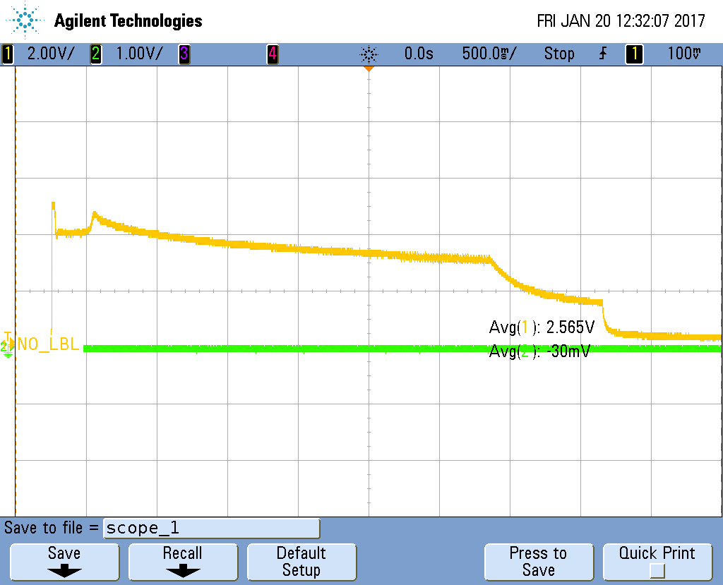
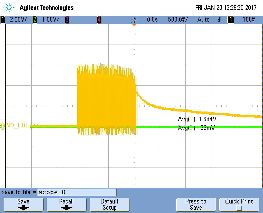
    I now have measurements of switch and out:

    1) Vout @ Vin = 8V

    2) SWITCH @ V_in = 5V

    Regards

    Carl Philipp

  • Okay,
    found it. It is so stupid, I am a bit ashamed.
    The cap C18 is pinswapped in the schematic, so I didn't notice it while soldering.

    Many Thanks for your help and apologies for my stupidity.
    Regards
    Carl Philipp
  • oh...I saw it, but i thought you used 22uf Ceramic cap(no +/- ,when soldering) follow our recommendation, not E-cap or Tantalum-cap(with +/-)
    and whaterver, It is good the issue is fixed now.

    BR,
    Yuchang