A related question is a question created from another question. When the related question is created, it will be automatically linked to the original question.
If you have a related question, please click the "Ask a related question" button in the top right corner. The newly created question will be automatically linked to this question.
Unfortunately there is no such data for the TPS54824EVM available from TI.
However even if such tests were done the results for EMI both conducted and radiated are so system, layout, and design dependent that it would not be relevant to any other implementation of the TPS54824.
That said the TPS54824 is a very capable part. Through using efficient layout and design techniques with optimal component selection for decoupling EMI to keep conducted and radiated EMI low the TPS54824 when used within its recommended operating conditions should be able pass CISPR22 and CISPR25 in your system.
Thanks for the reply. Yes, I understand that the EMI is very layout dependant, but some manufacturers are starting to give EVM EMI data as an indication of how the part performs.
It seems that quite a few are getting on the symmetrical pin-out bandwagon (e.g. LT8640, MPQ8636). But it makes sense to keep the circulating currents balanced so they cancel out, and hence low EMI. Some of these parts also have spread spectrum which is nice (e.g. LT8640, your LM53635). What would be nice for my design is something that can do 5-12Vin to 1V1out @ 10A, symmetrical pin-out, and spread spectrum. Something for the wish list…
Thanks for the part numbers. I was unaware that some suppliers have started inserting such information into their datasheets. I will have to keep on the look out.
I am curious if you have looked at the TPS56C215 it is a 12A part that has a similar symmetric configuration on the GND pins around the SW node. Also the fact that is a DCAP-3 control method it leverages a form of constant-on-time which is inherently somewhat spread spectrum. I am curious what you think after you have a chance to look at that part.
There might be a few other parts that could also fit the bill but that would be a good place to start in the TI catalog.
Yes I have been looking at the TPS56C215 and it is high on my list. I had not thought of the DCAP-3 control being SS, but that's a good point. Thanks for the tip! A bit of a shame that it can't sync to an external clock.
I'm also looking at the TPS54020 (and its module version LMZ31710 which shows EMI data) which can sync to an external clock, so I may add an external SS generator, although the pin-out of the TPS54020 is not symmetrical.
And finally I’m considering the TPS54A20. A dual phase 2MHz part with very small layout, but unfortunately it only goes down to 8Vin. I need down to 5Vin for auto cold-start.
Just thought I would give you an update on my progress...
Got hold of several evaluation boards so that I could estimate radiated noise. Used a near field loop probe and a Cleverscope CS328 oscilloscope which has a spectrum analyser built in. OK, it’s not as good as a proper EMI chamber, but at least it can give me an indication. Here are the results:
Test Board
Type
RMS noise
Spectral Peak
F peak
Vin Range
Part cost US$ (100)
Efficiency (data sheet) 12Vin, 1V1, 6.4A out
LMZ31710EVM
Module
95mV
-26dB
312kHz
3-17V
11.68
85
TPS54020EVM
Chip
117mV
-22dB
500kHz
4.5-17V
5.11
?
TPSM84A21EVM
Module
49mV
-33dB
1995kHz
8-14V
12.75
85
TPS54A20EVM
Chip
38mV
-35dB
3928kHz
8-14V
5.35
86
MPM3682
Module
78mV
-26dB
436kHz
4.5-18V
9.80
90
MPQ8636
Chip
94mV
-25dB
300kHz
4.5-18V
3.13
90
TPS56C215EVM
Chip
62mV
-29dB
1243kHz
4.5-17V
3.95
83
The TPS54A20 & TPSM84A21 are dual phase 2MHz parts and give the best performance for radiated noise, but they do not operate below 8Vin. There is an internal 7.65V UVLO which shuts the part down. So these parts cannot be used for the automotive start condition (ISO 16750 normal cold start 4.5V for 19ms, rising to 6.5V over 50ms).
Next best part which could keep running through cold start is the TPS56C215. It has symmetrical pin-out so good for EMI. So will use the TPS56C215 for the design.
Then I started experimenting…
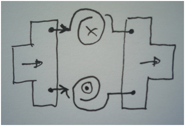
The idea of these symmetrical pin-out parts (e.g. LT8640, LM53635, TPS56C215, MPQ8636, etc) is that current flows in balanced loops to cancel out the generated EMI:
All good, except there’s only one inductor so it can’t be symmetrical and cancel out. So try with 2 inductors…
The LM53635 board has the most symmetrical layout of the ones I have, so modify it with 2x 4.7uH inductors in parallel. Placed them with “pin 1” in opposite directions so that flux will cancel; e.g. with current flowing from left to right, one inductor will have flux going into board and the other will have flux coming out of board.
LM53635 board: Original single 2.2uH:
LM53635 board: Modified with 2x 4.7uH, pin 1 opposite directions:
Frequency display: Dark trace 2.2uH original inductor, light trace 2x 4.7uH (peak about 6dB better):
Time display: Loop centred over inductor(s). Dark trace with 2x 4.7uH, light trace with original 2.2uH. For the 2 inductor case the flux is cancelled directly above the centre of them.
Using dual inductors seems to improve the peak radiated noise (at least for near field) by about 6dB, and directly above the inductors the flux is cancelled. This also has the advantage that the current is half in each inductor, so flux density and RMS losses will lower.
We will implement parallel inductors in our design.
I don't have the luxury of a proper EMI test facility to hand, hence the near field loop probe. It would be interesting if you, or your colleagues (perhaps in the LM53635 group) could test this idea with real EMI measurements. Just a thought…