This thread has been locked.

If you have a related question, please click the "Ask a related question" button in the top right corner. The newly created question will be automatically linked to this question.

LM25085 behaves strangely

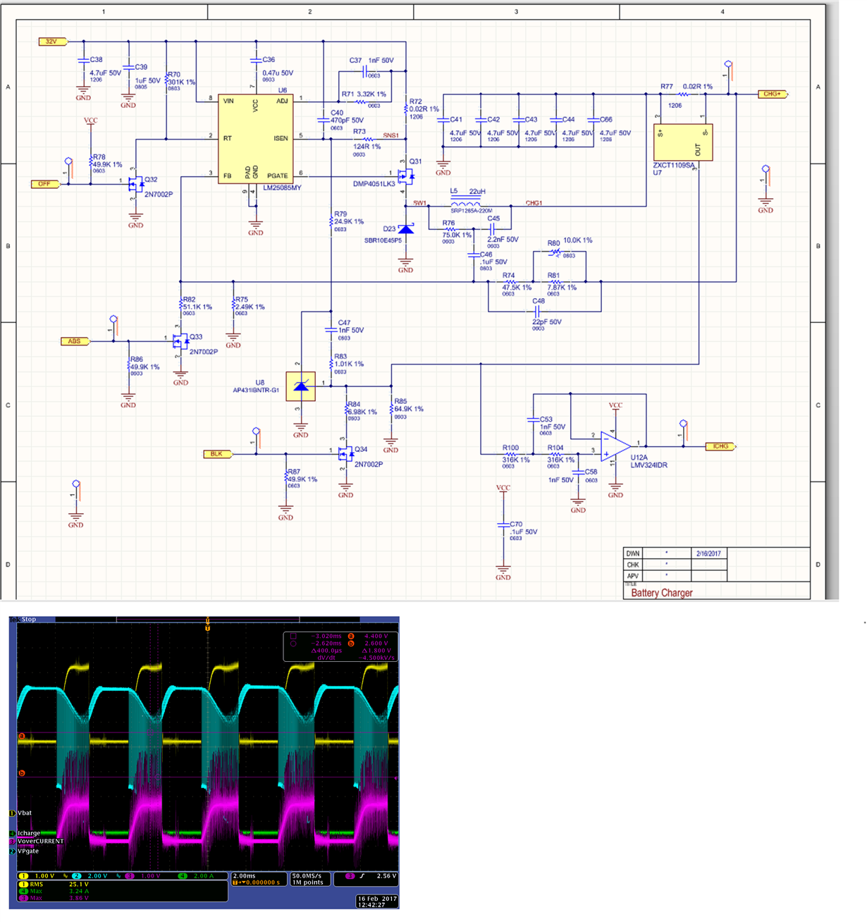
I am using LM25085MY as a constant current battery charger to charge 24V/55AH lead acid battery with 5A current. The schematics are attached.

However, the PGATE switches correctly for only about 1 ms, then it stops for about 1ms. The pattern repeats. The screen capture is attached.

Could anyone give me some suggestion?  

  • Hi,

    The feedback reguires 25mV of ripple to correctly operate the FB comparator. it need to be in phase with inductor current. Can you check that you have adequate ripple at the feedback node? another potential issue is through the current sense input. You may want to try decreasing Rsense and or increase the filtering at the current sense input?

    It seems to me, you have alot of external circuitry around the IC. Suggest running in constant voltage first and then start adding the additional constant current circuits to your IC and pin point which input Isense or FB is causing the issue?
  • Hi David,

    Thank you for your suggestions. I have done some more investigation, and I would like to give you some feedback. It seems that the problem is related to feedback voltage and soft start. My 55 AH battery has a floating voltage around 24V. The designed output voltage according to FB is 27.3V. FB should be reduced to meet the 24V voltage because the battery resistance is very small. It seems to me the FB is reduced to 0V, and it ramps up according to the soft start time (2.5 ms). Is there any method to prevent the reference drop to 0V?

    According to your application note www.ti.com/.../snva486a.pdf, even if VOUT drops from 5V to 1V, constant current can still be achieved. In this case, the FB reference voltage must have been reduced.  

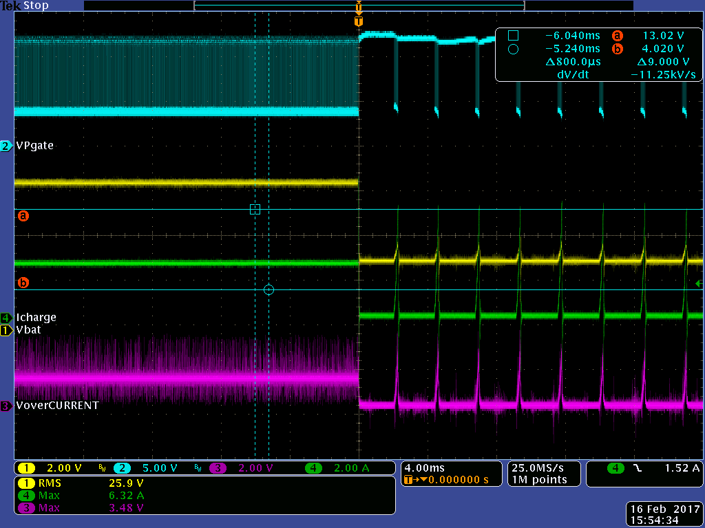
    The attached figure shows the response if I short circuit the serial resistor that connected to the battery. The yellow trace is the battery voltage measured before the serial resistor, the blue trace is the PFET gate driver, the green trace is the charging current, the pink trace is the feedback ISENSE signal. The system works until I manual short circuit the serial resistor.

  • Hi David,

    Thanks for the feedback.  From your description above, I understand your approach, up to the point where you discuss shorting out the Series Current sense resistor?  If you do that, you will lose control of the current loop that is controlling the output current.  So I am wondering why you are implementing this test.  Can you help me understand?  Thanks.


    David.

  • Hi David,

    I may have explained the test inaccurately. I did not short the current sense resistor. What I did is that instead of connecting the battery directly to the output, I put a serial resistor to the battery to increase its "internal resistance". In this way the output voltage of the PWM controller can reach 27.3V that a fully charged battery may reach. The internal resistance of my 55 AH battery is almost 0 ohm. If the output voltage of the PWM controller is 27.3V, huge output current will flow to the battery, because there will be 3.3V voltage drop across an almost 0 ohm resitor.

    The reason that I am testing this is that I do not know if the internal reference voltage for FB is reduced correctly under an over current condition. In fact, I did not short the serial resistor in the first few tests, but to reduce its value. From my understanding by reading your application notes, 24V output voltage meets the voltage feedback loop requirements under the 5A constant current output condition, only if the internal reference voltage is reduced.

    Best regards

    David C.

    Mircom Inc.
    25 Interchange Way, Concord, Canada
  • The Feedback voltage is reduced under an overcurrent condition.  If you want to test this, I would try increasing the RSEN (R72 on your schematic) to a value that will not sustain the Current regulation level without hit the current limit threshold.  Once the current limit threshold is exceeded, the Voltage at the Feedback should reduce.

  • Hi David,

    I think the chip forces it to work in a discontinuous mode. In page 14 of the datasheet, it says in medium to heavy load, it works in discontinuous conduction mode. This is not what I need. Is there anyway to force it to work in continuous conduction mode? What are the criteria to judge if it is light loaded, medium loaded, or heavily loaded?

    Thanks!

    David C.

    Mircom Inc.

  • Please forget my previous post. I think I get some ideas as what is happening there. But it is not correctly described.