This thread has been locked.

If you have a related question, please click the "Ask a related question" button in the top right corner. The newly created question will be automatically linked to this question.

TPS53355: WEBENCH Design tool followed exactly, unexpected results.

Part Number: TPS53355

I have recently attempted to use the TPS53355 for a simple high-current buck converter. I used the WEBENCH Design Tool to get an automated design from TI for the following specs:

  • Vin: 6-15V
  • Vout: 5V
  • Iout: 30A

I then looked over the schematic and ordered all the required external parts. I created the circuit but it gave quite odd results. To test it, I used an input of 9.12V from a 9V battery. The output resulted in roughly 2-2.25V rather than the expected 5V. I tried an input of 12.91V from another supply and the circuit output was roughly 3.6-3.7V. I then realized that through creating the circuit, I had forgotten to put the TPS53355's PWPD to Ground. So I put it to ground and the new voltage was 0V, regardless of input voltage. I rebuilt the circuit 4 times to ensure I didn't do something wrong but the same results occured each time. At this point, I assumed at some point I may have killed the TPS53355 so I ordered a new one. It can today and when I tried to use it, the same results as previously mentioned occured (albeit, at about 0.2V higher).

If someone has any reasonable explanation for what I may have done wrong, please let me know. I'm especially confused by the fact there is only an output voltage without PWPD connected to ground.

Thanks.

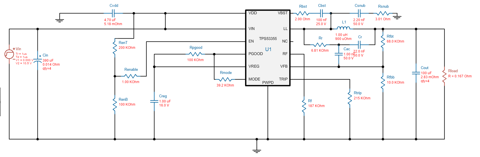
(The schematic that TI generated for the given specs is shown below)

  • Switching dc/dc converters are sensitive to PCB layout.  Did you follow the datasheet layout recommendations?  Can you post your PCB layout?

  • Currently, the setup is actually in breadboard-form to show a working proof-of-concept before investing in the PCBs and SMD components (the TPS53355 is on an SMD to DIP breakout). Is such a setup impossible be made to work?

  • I don't know if it is "impossible", but I can tell you that most people that try it run into problems.  There have been several posts on this topic over the years about this type of issue.  I suppose if anyone has successfully done it they would not post here though.  I would recommend that you acquire a TI EVM and modify it to your specification.

  • I'm not sure if I can invest in the $50 for an EVM at the moment, especially given I've already invested in the parts on their own. Is there anything I can look into that could possibly lead myself towards getting this working on a breadboard?

  • I'll ask around to see if anyone has any ideas.  You might possibly get TPS53355 to regulate on a double sided copper board.  Hand cutting that etch pattern will take some precise work.  But you will never get anything close to 30 A out of it without a well designed multi-layer PCB.  The exposed thermal pad must be well connected to sufficient heat dissipating ground copper.

  • Alright, thank you. If end up getting this working on the breadboard and can move on to PCB, what specifics are really necessary in the design. The technical documentation mostly just mentions the heat dissipation for ground, keep capactiors close to the power in/out and keeping various other things away. Is there design technicalities to take into consideration beyond those ones on there. I only ask because even on the breadboard most of those are followed in the setup I have so something else might explain why its not working.

  • A bit of an update,  I moved the circuit to a perfboard seeing as the inter-pin capacitance of the breadboard was likely a part of the issue. After moving it to the perfboard, I get 2.55V out but that voltage is fairly consistent from 6V-15V input. So it seems the circuit is now working except for not outputting to the correct voltage (5V). Any idea?