This thread has been locked.

If you have a related question, please click the "Ask a related question" button in the top right corner. The newly created question will be automatically linked to this question.

TPS54332: Low output voltage - does not comply to the Vsense

Part Number: TPS54332

Hi,

I've encountered a weird issue.

I have a board with TPS54332 to regulate 12V out of 20V input. the 12V feeds 4 more DCDC (0.9/1.2/1.8/3.3).

I've made two assembly batches. 

The first batch (20 pcs, 2 months ago) was all machine assembled. And I've not encountered any problem with power management.

With the second batch (13 pcs, same PCB batch)  few components were missing and therefore were soldered by hand. The relevant parts (for this thread) that were soldered by hand  are the compensation circuit, the SS capacitor and the SCHOTTKY diode.

On half of the boards, hence, 7 boards I encountered a problem that the Vo is stuck on ~2.85V.

Above is the circuit.

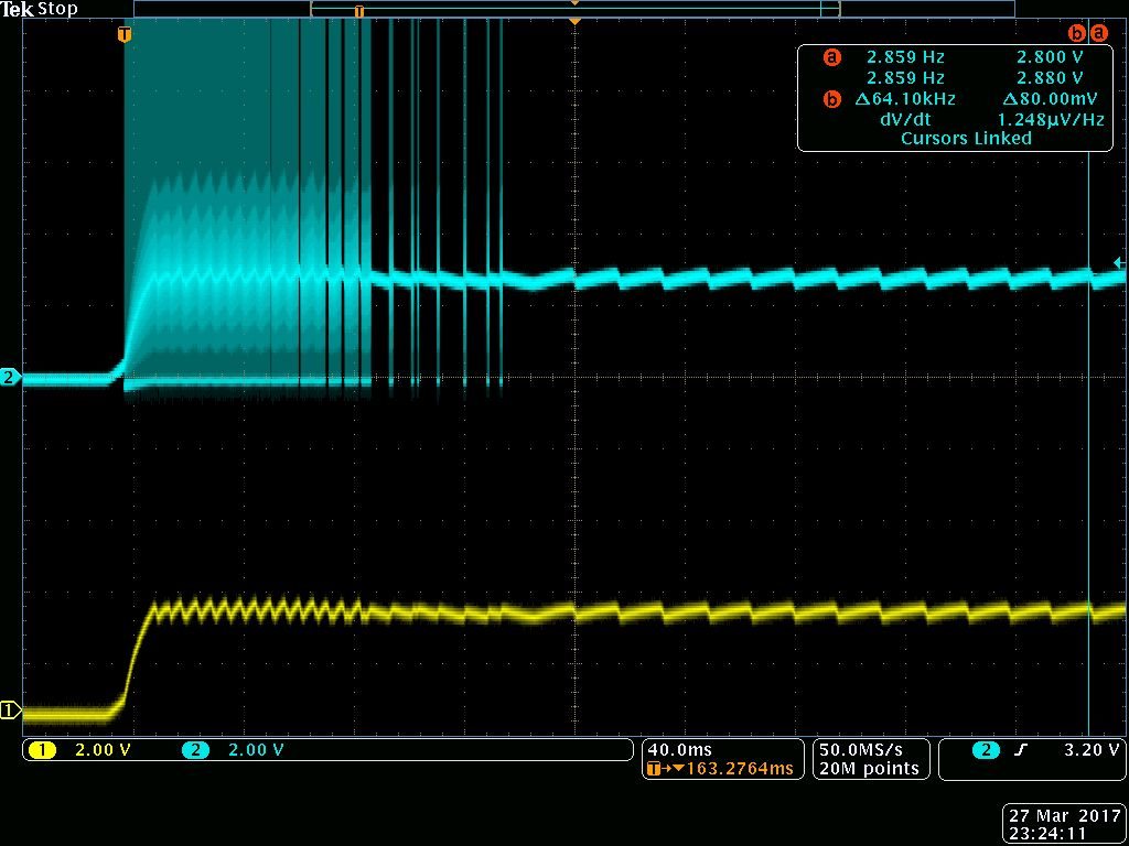
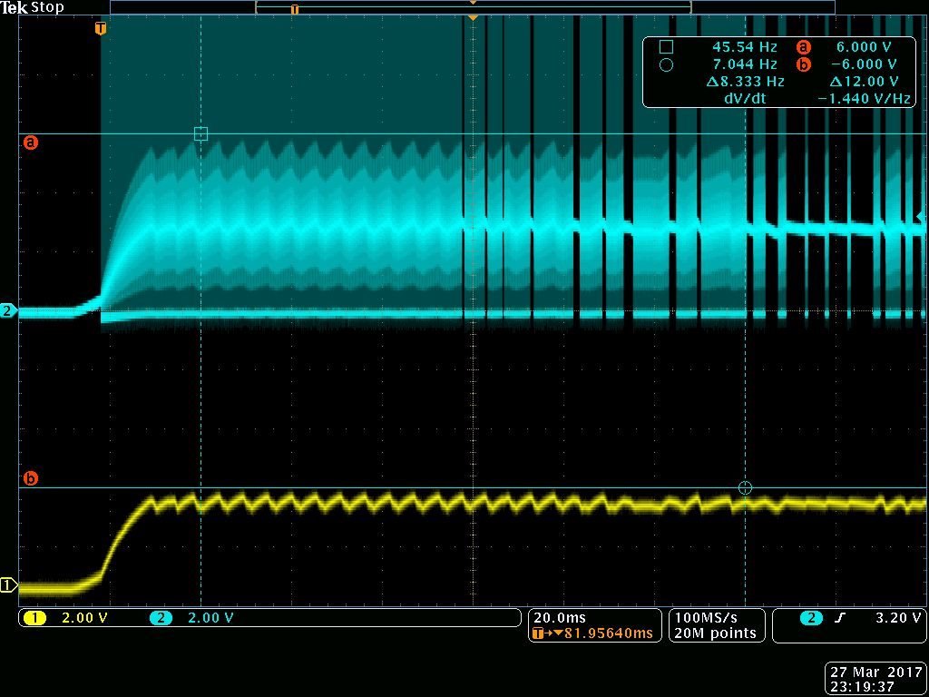
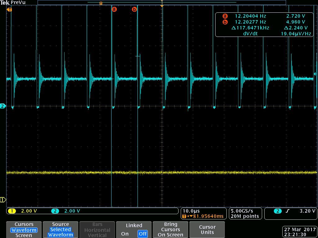
Below are the screen shot from the Oscilloscope when powering up. probe #1 is the Vout (12V after the inductor) and Probe #2 is the PH pin.

As you can see above, after about 150ms the PWM stops , and even before, the Vout doesn't rise above the 2.85V.

Because I have two batches of production and one of the batches works well I assume I have a marginal situation which roll over to a fault when I solder by hand (capacitance and stuff)

1. what am I missing? why the same design which was taken from the WEBENCH doesn't response the same?

2. Regarding the Compensation filter. How does it effect the output? are the values must be followed exactly?

BR

Itay

  • If your previous circuit works properly, then I think you had best go back and re-check your component values and soldering. Since we are only talking about 13 boards, I would be inclined to re-do all 13 completely to ensure all values are correct and that none of the ICs were damaged.
    Compensation is required to stabilize the loop. There are many possible combinations that will result in a stable circuit, but if you are not experienced, I would strictly follow the Webench design.
  • Hi John,

    Thanks for your reply.

    The components looks good and OK (after few verification and measurements).

    I kept debugging and isolating the problem. And I've reached to a dead-end, maybe you have some more insights.

    I've disconnected the power stage from the rest of my board and each part works and response good.

    see attached picture:

    When disconnected from the load, the output of the TPS54332 is correct and reach 12V (as expected). In parallel, when I've connected a desktop power supply to my circuit it showed 140mA, so there is no short or very high load.

    I still didn't get an hold on a "load resistor" to test the TPS with a controlled load, I guess that when I'll test it with a load I will bump into the same phenomena, but I don't see any reason why the TPS can not drive the 140mA.

    Any Ideas?

    [Edit]

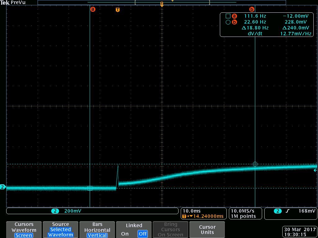
    Also, I've found that the SS pin doesn't rise above 0.2V

    This is the SS pin voltage at power up.

  • Hi,

    Based on you have OK board, Looks it is not very hard to confirm the root cause,

    1, First, Are the layour same for these two batch board, if same, layout should be OK.

    2, Change all components of the first batch(OK board, test before rework) to the second batch not good board, check if the board can work normal? if ok, it is components issue or solder issue. if no, change one more with the same action to confirm, if still the same, maybe related with PCB.

    BR,

    Yuchang

  • Hi Yuchang,

    I actually did it already.

    I had a hard time to hand solder the original schottky diode, it is very small footprint and the pads are on the bottom, so I've soldered a larger SMT package between the PH pin and the GND. Unfortunately it did not fix the problem. SO, I took an old board that worked fine, removed the original diode and soldered the new one as I did for the latest board, and the board failed to power up, the same as the latest one.

    I did it with two different diodes, but no luck. the output reach 2.85V and the SS pin is 0.2V. And it is on a perfectly working board.

    I believe that the 0.2V is the Vf of the discharge FET. I guess it enters into fault condition and cannot recover, for some reason.

    The original diode is NSR20F30NXT5G (30V , 480mV Vf, @2A)

    The new ones are:

    1N5820GOS (20V, 400mV Vf @ 3A)

    DFLS220LDICT (20V, 350mV Vf @ 2A)

    Maybe the diodes or the soldering are not perfect, and I've expected to see maybe non ideal voltage output (ripple, low utilization or other non ideal situation), but I didn't expect such a behavior of non functioning, in a very low load (140mA).


  • Hi
    So as you said, you alread remove all components from the fisrt batch(20pcs) board to the second batch(13pcs) board, but still cant work, right? BUT that doesn't make sense if you haven't change layout. after remove components, the second batch board have the same layout and same components as the first batch, the borad should work as the first batch can work normally.-------"Remenber use all components on the first batch board, not from your lab."
    NSR20F30NXT5G Diode should be OK for this.
    Another suggestion, you can set a lower output voltage such as 2.5Vout follow typical circuit fig12 to double check.
    Finally, recommend you add a discharge cap, parrallel with SS pin cap, like Fig12 R4 in Page14 of DS.

    Regards,
    Yuchang