This thread has been locked.

If you have a related question, please click the "Ask a related question" button in the top right corner. The newly created question will be automatically linked to this question.

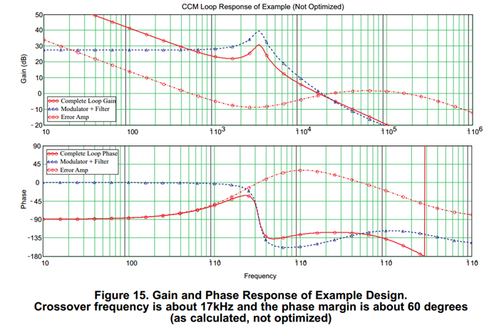
Gain and Phase Response of Example Design in Application Report SLVA301

Hello,

After studying all the  Application Report SLVA301 - Loop Stability Analysis of Voltage Mode Buck Regulator With Different Output Capacitor Types – Continuous and Discontinuous Mode, I create a script in Matlab with all the steps described in the Design Example.

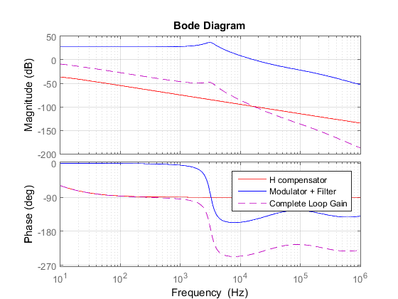
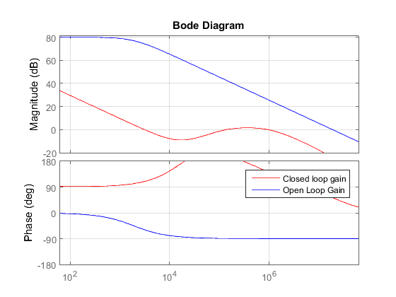
Despites all the component values calculated be exactly equal those showed in Aplication Report, the bode plots of the compensator does not are equal to that showed in Figure 15.

Below is the image copied from SLVA301 application report and the bode generated by my code in Matlab.

The filter transfer function are equal, but the error amp or compensator does not.

Someone else that already studied this application report could help me with this? Why the compesator bode plot does not are like the SLVA301 application report? I'm inserting the matlab file used to calculate.
Thank very much.

slva301.zip

  • Jose,

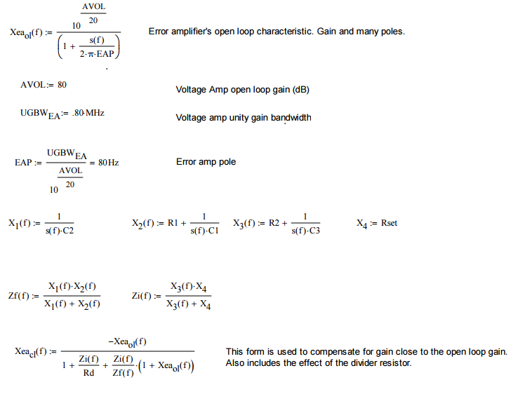
    I am not too familiar with MATLAB, so I have recreated the compensator in MATHCAD  (attached pdf) and found the  curves correlate with the Application Report.

    My first thought is to review your calculation for the amplifier closed loop gain.

    Brian

    Mathcad - Error Amp Type 3.pdf

  • Hello Brian Lynch.

    Many thanks for the reply, but I have some doubts:

    1 - In SLVA301, the error Amplifier Compensation Pole is given as 300 Hz, but you use 80 Hz. Can you explain me why the difference?


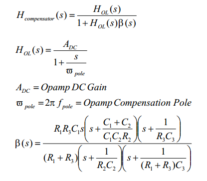
    2 - I noticed that you calculated the compensator closed loop transfer function in a different way from that showed in SLVA301. Below there are the both methods.

    Yours method:

    MatchCad calcualte

    SLVA301 method:

    SLVA301 Method

    If I do like you, I can achieve exactly the same result. Below is the image generated using Matlab and doing computation your way.

    Do you have any idea why these two methods give me different results?

    Thank very much again.

  • Jose,

    To your questions:

    The method I use to calculate the pole frequency and the error amplifier transfer function is simply classical circuit theory. Why The author used 300 Hz instead of 80 Hz I cannot say. 

    For the compensation transfer function (without going through the task of algebraically manipulating the MATHCAD form into the form used by the author), I suspect there is a typo someplace - either in the note, or in the MATLAB form . The plot you showed earlier is so far off from what we would expect given the component values, I cannot imagine the difference is due to a design methodology.

    Brian

  • Hello, Brian.

    I gave up understanding why the closed-loop transfer function in SLVA301 was written that way.
    I will continue using the formula you gave me.
    But honestly, I could not get into the closed-loop equation you showed. Can you give some reference or step by step how to get into the Xeacl equation?

    THanks