This thread has been locked.

If you have a related question, please click the "Ask a related question" button in the top right corner. The newly created question will be automatically linked to this question.

LM5022: How to determine the system stability when using LM5022 current control

Part Number: LM5022

Dear Colleagues of TI,

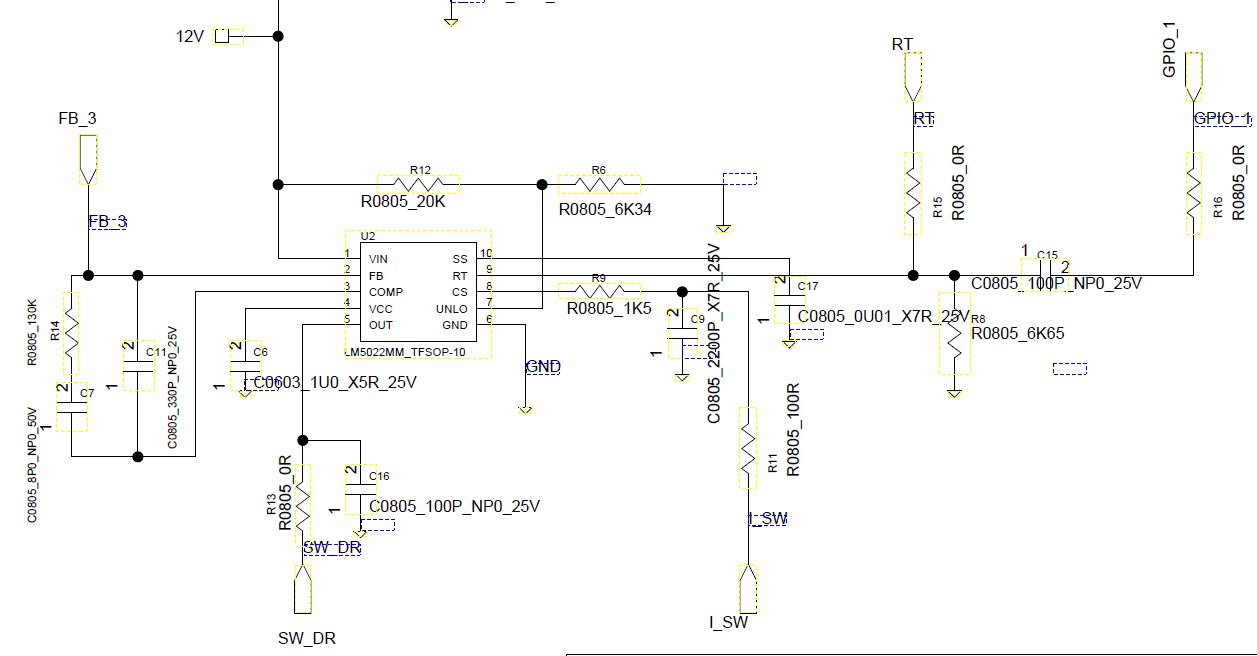
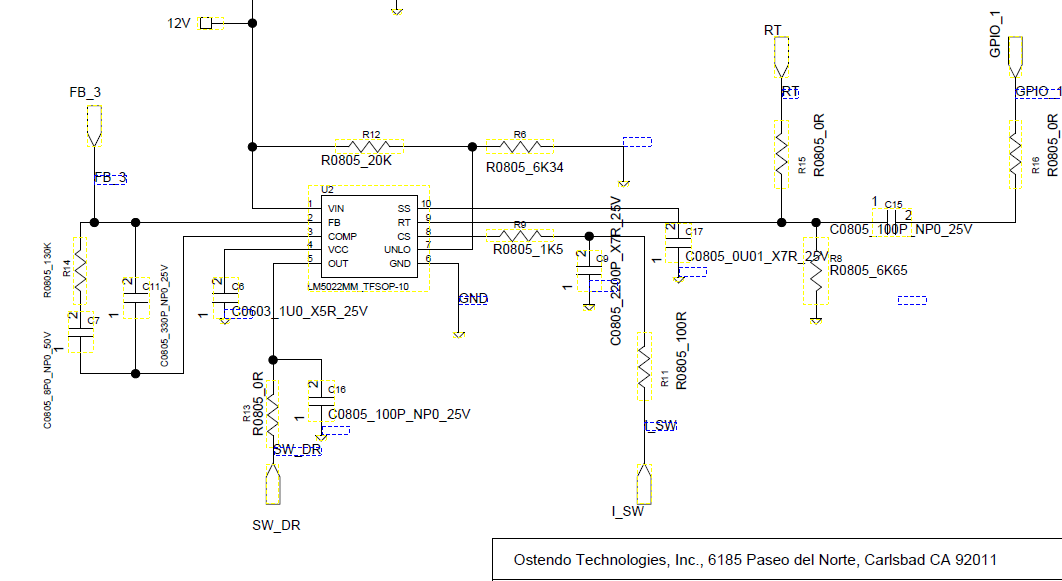
TI's specification of LM5022 has detail described the loop compensation. I used the same Methodology by MathCad and then I got the compensation circuit. I used the concluded calculation to design the actual boost circuit. But in lab test, I found when input voltage in range of 0.4V to 0.6V, the output is only 1.2V about 50% of target voltage 2.5V. If I can improve to input voltage to 0.8V or above, the output voltage can reach to 2.5V. I would like to know my control loop is corrective?

Please see attached.

From the Bode Plot, I could not figure out the Gain and Phase Margin.

  • Hi Johnson,

    Please provide a schematic and the application details (Input Voltage range, Output voltage and load current).

    At first glance it looks like the 1uF and the 8pF capacitors in the compensation network might be need to be switched.

    Thanks,

    Garrett
  • Dear Garrett,

    Thank you very much for looking into this case.

    Please see attached schematics. In order for you to be easy to understand, I sketched the power stage schematic. The output capacitor group have total 11 pcs of 100uF/10V capacitor, ESR of one of them is 10mOhm. The input voltage from 0.35 to 0.6V, load current about 1 A. This is one solar cell design application.

    If you need further info, please let me know.

    Thank you very much!

    Johnson


  • Hi Johnson,

    What is the value of the current sense resistor?
    Is the 12V rail supplied at 12V always?
    Can you please remove C0805 that is on the OUT pin? This might be causing some issue with turning the MOSFETs all the way on?
    What are the MOSFETs that you are using?

    Thanks,

    Garrett
  • Hi! Garrett,

    The current sensor resistors are two 5 mOhm resistors in the parallel, then total is 2.5 mOhm resistance.

    Yes, 12V rail is always 12V. It is supplied with another boost IC to regulate 12VDC. The rail will start up early than the LM5022 power system.

    OK, I will removed the C16 on the output pin ( pin 5 ) and it is only 100 pF. The MOSFETs as seen in the schematic are 5 STL51N3LLH5 in parallel.

    Thanks,

    Johnson

  • Hi! Garreet,

    Do you have further help on this case?

    Johnson

  • Hi! Ti,

    I believe this case is not solved. I didn't get the reason why the output is not reaching the target voltage when input in the low value of 0.4 to 0.6V.
    Thanks,

    Johnson
  • Hi Johnson,
    There is not much clue of the issue on your posted schematic. Do you have any bench test waveforms showing the MOSFET gate voltage, switch node voltage, etc? Hope to resolve this quickly.

    Thanks,
    Youhao Xi, System and Applications Engineering, APP-BMC-BCS, TI