I'm implementing a boost converter and decided to use the TPS61045 since I need the output to be digitally adjustable between 10 V and 28 V.
When testing the IC - with the external components on a breadboard - I run into some troubles with the output capacitor and the load in general:
1) At first I implemented the configuration in such a way that the output voltage would be 10 V. Using a 1 uF output capacitor produced the wanted results but when I changed the capacitor to a value of 2.2 uF something happened, which damaged the chip. The chip now produces 0 V at the output and draws a high current constantly from the 5 V power supply, the IC gets really hot. I concluded that the SW node is shorted to ground constantly so the chip is not switching, and therefore the energy is not delivered to the output capacitor.
2) If I stick to using the 1 uF capacitor at the output it works, as previously mentioned. But then when I connect a 1 kohm resistor to the output the chip dies. Now nothing is being produced anywhere and no current is being drawn from the power supply. According to my calculations, the configuration should be capable of delivering the 10 mA to the load.
Do you have any idea of why this might happen? Could it be a stability issue and do you know how I could solve the problem?
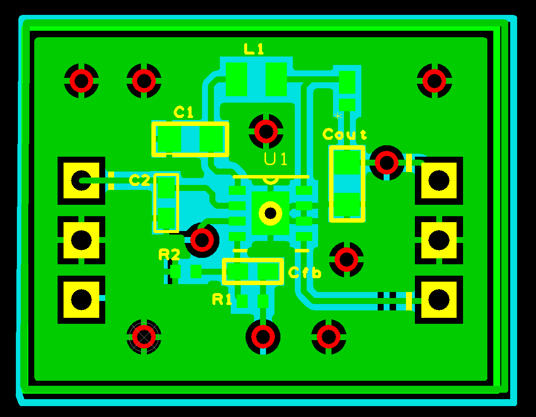
To give you further insight I listed the external components below:
Inductor: 10 uH, Input capacitor: 10 uF, Bypass capacitor: 100 nF, Resistive Divider: 2 Mohm and 270 kohm.
I have also made sure that all the components can handle the required voltages and currents.
Thank you in advance!