This thread has been locked.

If you have a related question, please click the "Ask a related question" button in the top right corner. The newly created question will be automatically linked to this question.

LM5022: Suitability of LM5022 chip and problem solving for boost converter

Part Number: LM5022
Other Parts Discussed in Thread: LM5122

I have a boost power supply application that is somewhat beyond the limits that is supported on Webench. I chose a design that is about as close as I could find and planned to modify it.

Here are my requirements: Input: 10-36V, Output: 48V, Current: 13 amps, nominal with up to 30 peak amps

The power supply will be used to power a DC motor in a large power tool. I have added 10 MOVs to the output circuit, mainly to protect the output diode, as well as the other circuits.

Webench provided a 10 amp suggested design. I made a PCB for the circuit and it boosts the voltage to 48V with no load. It seems to work Ok at about 3 amps. But if put a 10A load on it, the chip and the MOSFET fail and have to be replaced. I would think the cycle-by-cycle current limiting feature would protect the MSFET and the chip from overcurrent damage, if the design is correct. The circuit also seems a bit unstable at higher currents, meaning the output current goes up and down before the circuit fails.

I have a few basic questions, to begin with:

1. I would like to know if there is any reason I cannot use the LM5022 chip for the 13 amp/30 peak amp application. The datasheet does not say there is a current limit, and the chip doesn't contain any power FETs or handle the high current directly.

2. I am puzzled by the failure of the LM5022 chip. I have replaced a couple of them and it's a mystery to me why they're failing. Any insights will be very helpful.

3. I am entering the dozens of formulas that are provided in the datasheet to calculate the values for each part, and checking the spreadsheet calculations by the examples in the datasheet. I will then use the spreadsheet to calculate the values for the higher current. Do you think there will be a problem with that? I'm assuming I need to use 30 amps as the output current, even though that is the peak amps.

4. Do you have any other advice or suggestions you think I should know about?

This is a proof of concept prototype for potentially high volume application, and worthy of some good technical support. I'm on a short time frame and I need to get this circuit working next week. I'm not a power engineer, and my experience is with lower power boost regulator applications. Any help you can provide will be invaluable. If there is a better chip to use in the production design, that's no problem at all. But I have a lot invested in the LM5022 and not much time to change direction, if the LM5022 chip can do the job.

Thanks very much.

Charlie Weisel

  • We started working on your request. TI engineer will reply as soon as possible.
  • Hi Charlie,

    Typically for this a high power application like this I would suggest using the LM5122 in multi-phase operation. Multi-phase operation allows for each phase to handle lower current and therefore less stress on the components and smaller physical size. For this application do you need a non-synchronous controller? Typically for high power like this a synchronous converter is desirable to help reduce conduction losses increasing efficiency.

    If it is possible to post a schematic please do so as this will give me more insight to what might be causing the convert to fail. If not please contact me directly at g-roecker@ti.com

    There are a number of reasons that converter could be failing. My first guess would be to that when the MOSFET fails the this is also damaging the LM5022. If the MOSFET has a large gate charge it is possible that the MOSFET is not turning all the way on as the gate driver is only 1A which is relatively small for such a high power application. It is also possible that some component is not rated for such high current.

    The LM5022 can be used for an application like this but based on the component selection there might need to be some extra circuity. I will discuss this more when I have a schematic to review.

    Please let me know if you have any questions.

    Thanks,

    Garrett
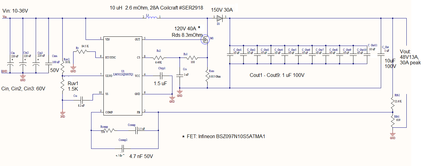
  • Hi, Garrett. Thanks for the fast reply. Here's the schematic. The larger font shows parts that have been changed from the original Webench design, to allow for higher current and voltage. Also, Ruv1 allows UVLO operation at a lower input voltage (10V). The only reason I would like to stay with the LM5022 for this prototype is the time factor, since we already have a PCB for this design and some experience with it. If starting over with the LM5122 is so much better that it would allow us to have a working circuit sooner, we could do that. I agree that the LM5122 may have failed because of the MOSFET failure. I suspect inductor saturation at the higher current, possibly leading to failure of the PWM duty cycle and overheating of the FET.

    I have been considering increasing the frequency and/or inductor size, which is why I am working on the calculations to determine the part values. We can accept a somewhat lower efficiency, since the starting point was about 97%. I'd like to stay in the upper 80% range.

    Thanks very much. Charlie

  • Hi Charlie,

    I have responded to you directly. We can continue the conversation over email.

    Thanks,

    Garrett