This thread has been locked.

If you have a related question, please click the "Ask a related question" button in the top right corner. The newly created question will be automatically linked to this question.

TPS61028: EN pin problems after -8kV ESD testing

Part Number: TPS61028
Other Parts Discussed in Thread: LP5907, TPS61029, TPS61020, TPS61252, ESD401

Hi all!

We tested our device  in an ESD testing laboratory, and we fail on -8kV voltage (the +8kV was OK).

After i take apart the whole device , and looking for errors, i found out that the problem is with the TPS61028 , which is providing us an 5,4V for our 5V power supply LDO-s.

As i measure, the TPS61028 EN pin has a closure with the GND (measure about 5 Ohm-s).

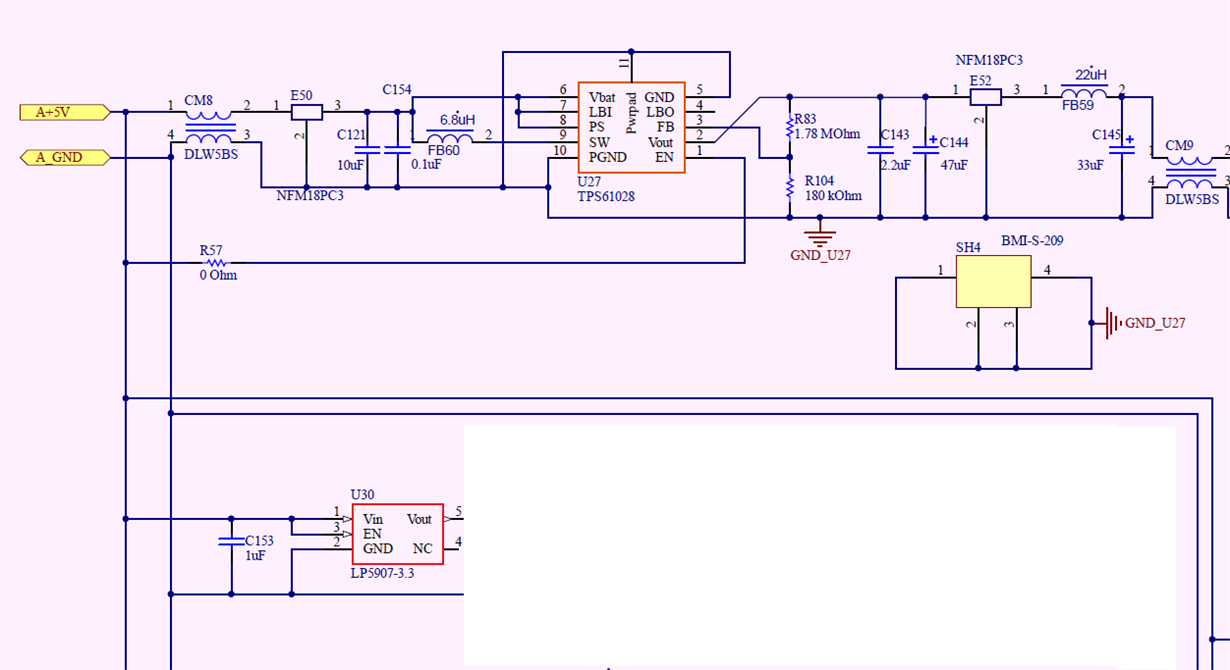
The TPS power input is on a power bus (getting power from a galvanic isolated DC/DC, 4.7-4.8V), with this voltage we feed a few LDO-s which does need a voltage above 5V to give us the other working voltages (3.3V,2.5V..etc). The strange situation is that there is no problem with any of the element which are located on this A+5V bus (what can seen on part of the schematic), but the problem is only with this part.

The enclosure is from metal, but we have a plastic cover.

The metal enclosure does not connects to the section where is the TPS61028 located. The metal shield is connected to the part (through a 6.3kV, 1000pF capacitor) on which is the galvanic isolated dc/dc input part.

Between the DC/DC input output island is also a 6.3kV capacitor (2.2nF).

So the matal enclosure is not connected electrically to the TPS61028.

we checked the whole board, and the problem is only with the TPS61028, and only with its EN leg...

If i power on only the TPS, it is working(but it eats about 300mA by itself...., previously the whole board consume this amount of current)

Currently we are thinking where the -8kV comes in, and how is it possible that no one of the other elements(LP5907, TPS73125, etc) located on the same A+5V bus are fine, and without any problem.

Did someone has same situation , or similar with this TPS61028?

Thanks in advice!

Best Regards

Lou

  • We started working on this request. TI engineer will reply as soon as possible.
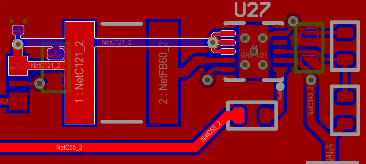
  • I am thinking maybe there is high voltage coupling into EN pin and destroy the IC, considering high impedance of the EN pin and the long routing in PCB. could you add a capacitor at EN pin and place close the IC?

    i also check you PCB, the routing of the C143, i would suggest to place it at the same side of the IC, and connect with IC VOUT and PGND pin with direct and strong routing.
  • Hi

    We also think that somewhere the high voltage comes in, but why only this part is than destroyed? On the same line as the EN pin is we have a few more elements connected (local LDO-s), and none of them is problematic.
    which kind of capacitor you think is the best to put?
    We also think if to put some TVS diodes on the EN pin line.
    we are also thinking to use some other pin-compatible parts instead of the 61028, if you prefer some other type (it is important to give us on its output 5.2V-5.4V).

    Best Regards
    Lou
  • a 10nF capacitor placed closed to the IC.
    a TVS is also good solution.

    there is not pin to pin device to replace the TPS61028.
  • hi
    Thanks for this information!
    Is there any specific requirement for that 10nF capacitor? Voltage rating? Size, type, dielectric... ?
    I assume that there is no other pin compatible from other series. The TPS61020, and the TPS61029 is pin compatible as i see (as they are inside same family). Is some of them better than the TPS61028? Or any other else from the boost converters? - i know that will initiate PCB design change, but at this point we have to look for all possible options.

    Best Regards
    Lou
  • 0402 or 0603 package 10V rating ceramic capacitor should be OK. i hope this capacitor can reduce the voltage coupling into the EN.
    TPS61020 and TPS61029 are the same device.
    TPS61252 can support the input/output condition. but not sure if it can pass the 8KV test.
  • Hi!
    Thanks for this information!
    If i put a TVS diode also on the EN pin what you prefer? Which would be the best for us?
    Some 1 channel TVS? As ESD401 ? Or some other type?

    If i put also a TVS diode on the input 5V power line (parallel with the C121 on our schematic) could it also help, or no need for this? What you prefer here for the power line?

    Best Regards
    Lou
  • Sorry, i know little about the ESD device or TVS device, so i can't give your suggestion.
    but i think TVS in parallel with C121 doesn't work, because the EN pin of our device is not connected to C121, and there is not high voltage in C121 as the large capacitance.
  • Hi
    When i mention putting the TVS in parallel with the C121 i think on the input voltage line.
    So my thinking was to put a TVS on the EN line, and also on the input voltage line (for sure).

    Best Regards
    Lou
  • Hi

    I take off the TPS61028 from the board, and measure the board itself, and the TPS.

    Its looks like the TPS itself is damaged, the EN leg has a closure to the GND legs.

    I put instead of this TPS61028 one TPS61020 (a sample what i order from TI), and also put a 10nF(0603 size, 50V, X7R type) capacitor between the EN leg and the GND.

    My operation was successful, the TPS is working, we got the 5.4V  on its output.

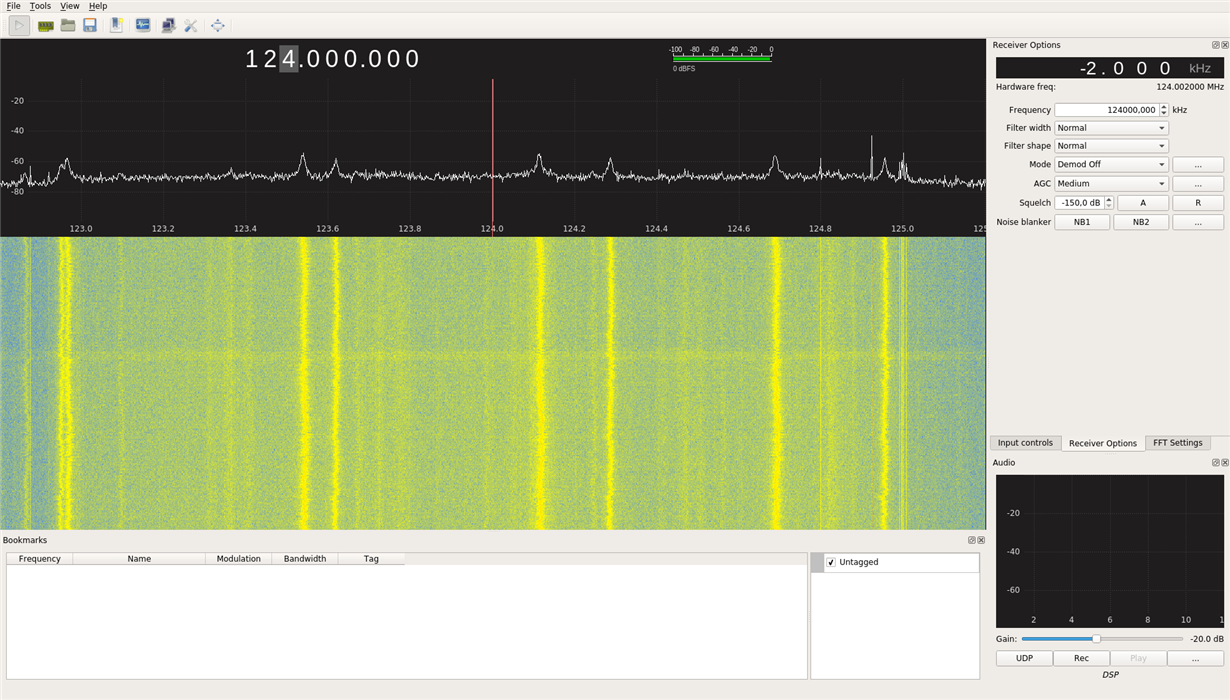
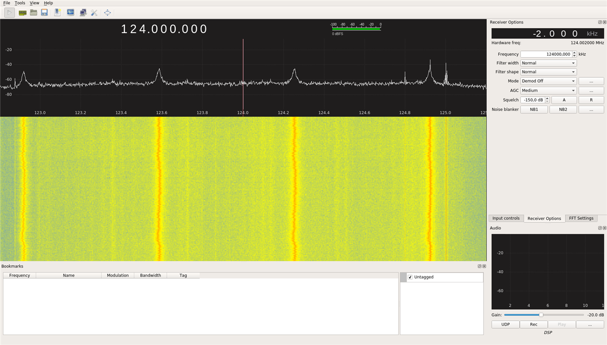
    I make some EMI measurement (with a simple Spectrum analyzer created from a RTL SDR dongle), and as i see we have a little bit increased noises on some frequencies - i have one other board with the TPS61028 installed.

    As unfortunately i dont measure this EMI noise on this location of the board ( above the TPS section) with the original stage(when the TPS61028 was installed also on this spot) at this point i dont know what was the original status.

    So it could happened that this is not because of the TPS61020.

    And at this point i want to ask, did you notice some differences in the  EMI characteristics between the TPS61020 and TPS61028 (when they are working in the same environment- same input/output voltages, same current consume parts attachet on the  Vout circuit, so same current demand) ?

     I put the 2 pictures:

    Spectrum @124Mhz above the TPS61028 section:

    Spectrum @124Mhz above the TPS61020 section:

    Thanks for any idea!

    Best Regards

    Lou

  • the EMI performance of TPS61028 and TPS61020 should be the similar. because the control principle is the same.
    are the operate conditions of the two system board the same? because the load condition may be a little different for each system board.