This thread has been locked.

If you have a related question, please click the "Ask a related question" button in the top right corner. The newly created question will be automatically linked to this question.

LM5088: LM5088-1 Failing, needing to be replaced.

Part Number: LM5088

Hi, I’m getting failures of the LM5088 part while powering 4 x Sanyo Denki SanAce40 9HV0412P3K001 PWM 12V fans.

I’ve used TI’s Webench to produce a 48VDC to 12VDC 10A buck converter with link shown below.

https://webench.ti.com/webench5/power/webench5.cgi?lang_chosen=en_US&DesignId=28

The failures happen when starting to run the fans at higher speeds, the buck converter supplying around 86 Watts

The 12V drops out leaving the LM5088 to just get hot.
Closer inspection shows a low resistance between the GND and VCC pins.

Replacing the LM5088 fixes the failed board, but will fail again upon performing the same test.

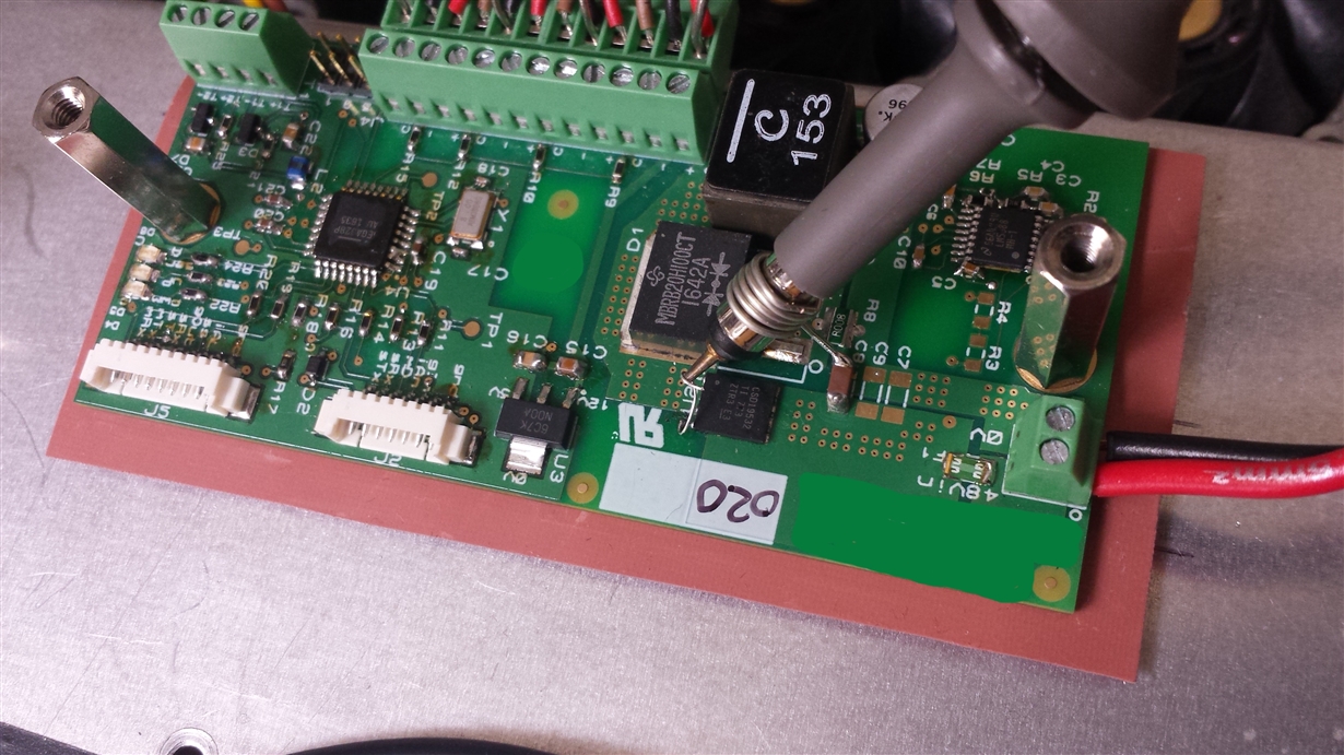
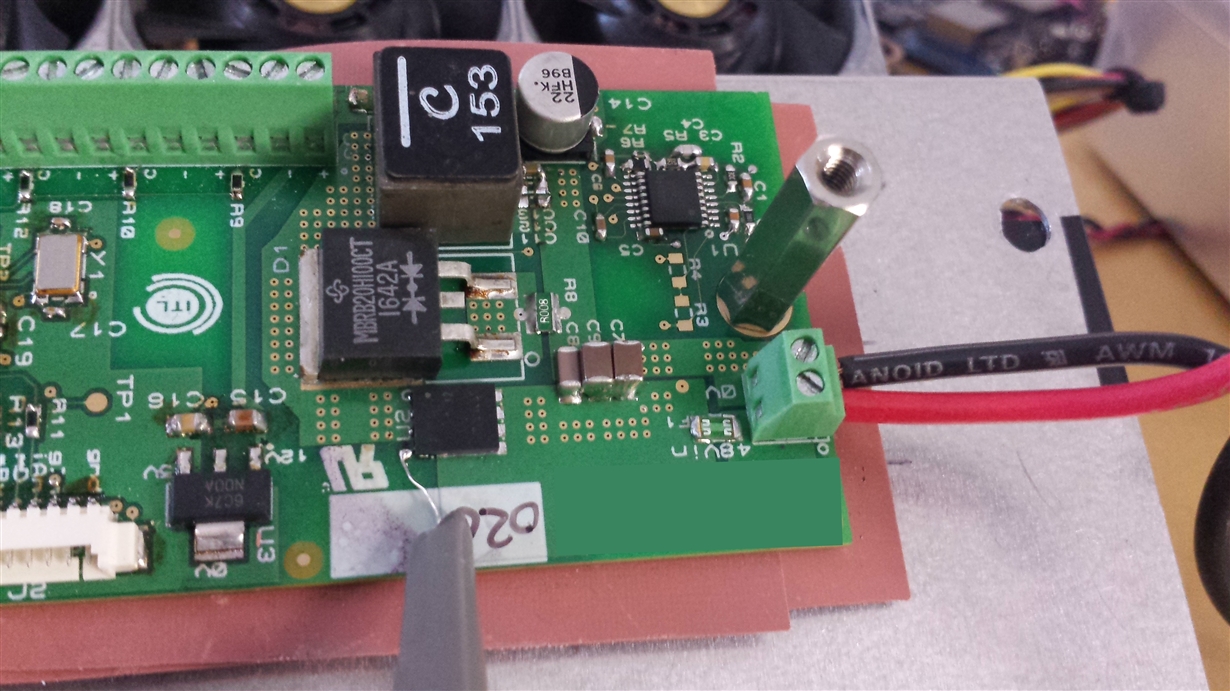
The PCB is mounted through thermally conductive material onto a metal plate for heat sinking.

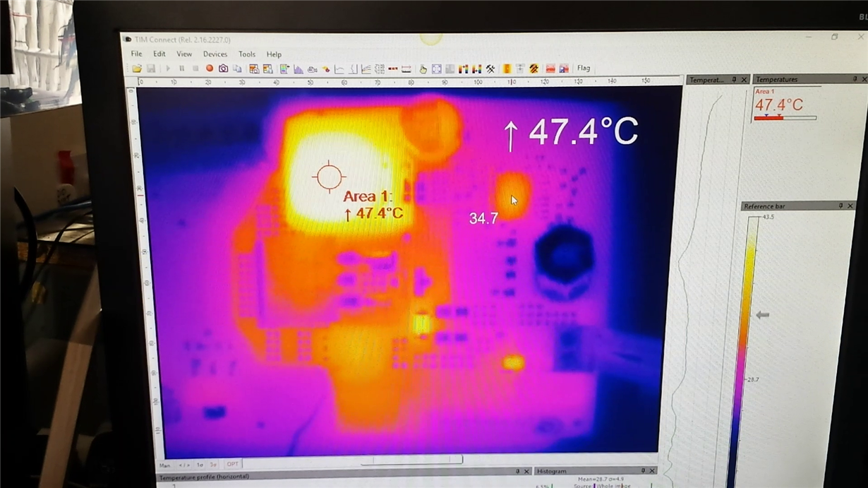
I’ve taken thermal images of the LM5088 case temperature and it only seems to be around 60 degrees Celsius at this point, I think there is a jump from 40 Degrees to 60 upon failure.


I’ve performed another load test with a purely resistive load of 1.65 Ohms.

The same issue happens again within a few minutes.

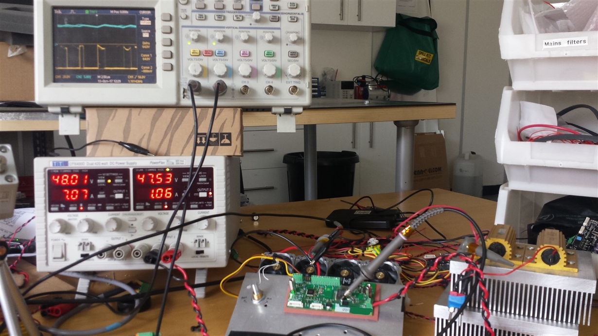
I’ve a video of the setup and a failure, it’s 135Mb and can post if there is somewhere to upload it to.


Is there a way I can tell why the LM5088 devices are failing?


Notes:

I’m not fitting RUV1 or RUV2 as I want the LM5088 to be always enabled.

Could this be an indication of an ‘overload’?
If so, would using the LM5088-2 device solve this problem?


Kind regards, Jerome

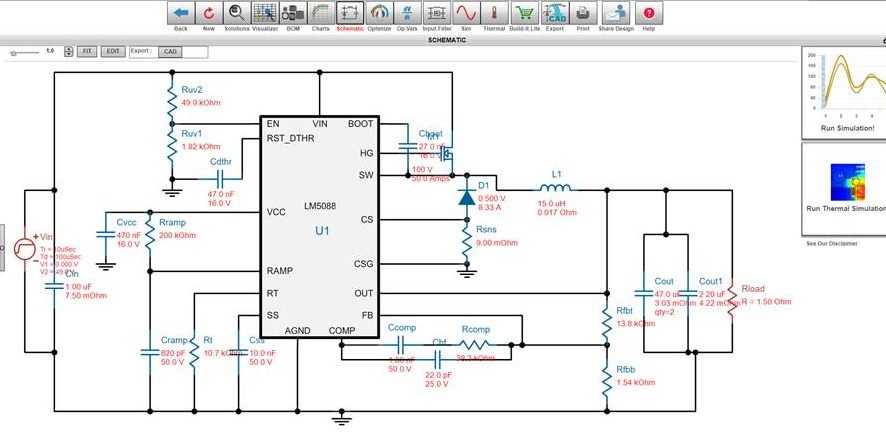
From Webench

Webench Bom

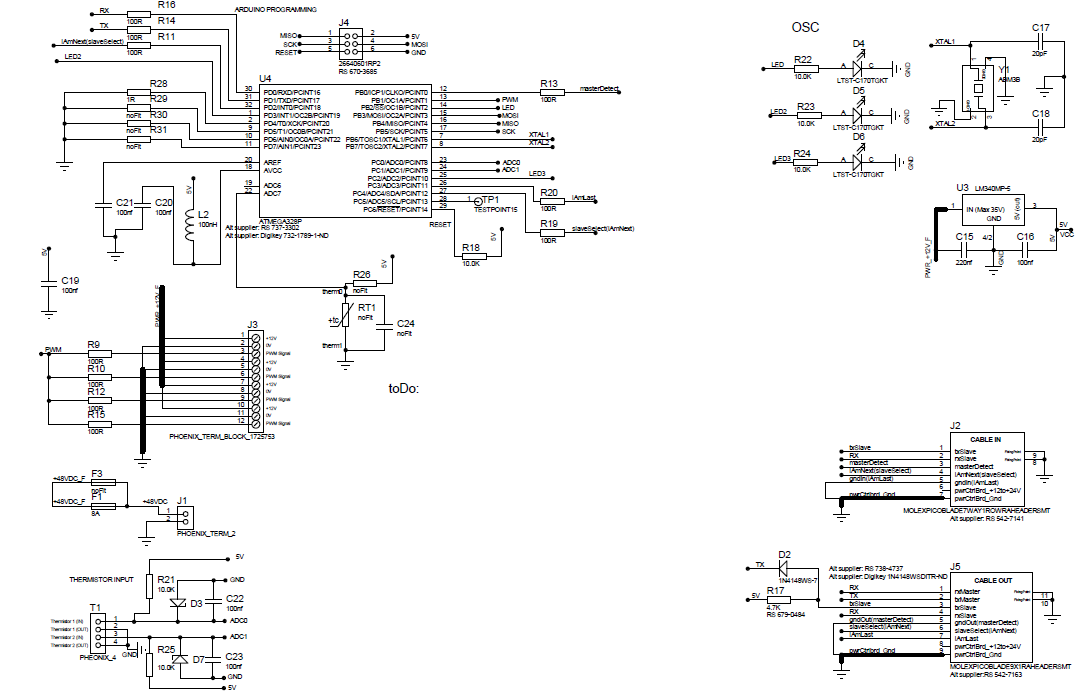
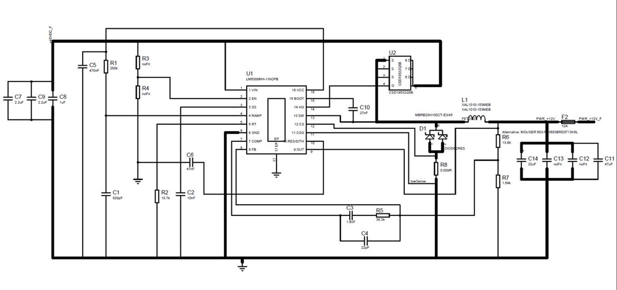
Schematic for our board sheet1

Schematic for our board sheet2

Our bom

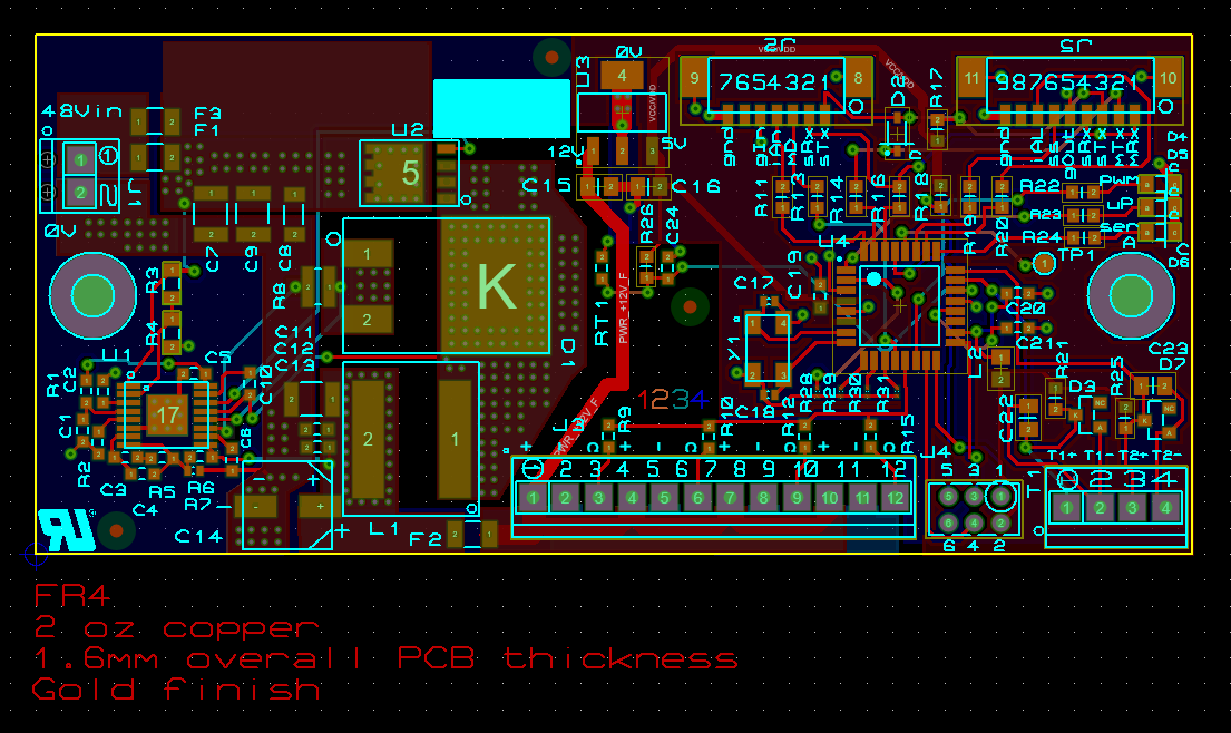
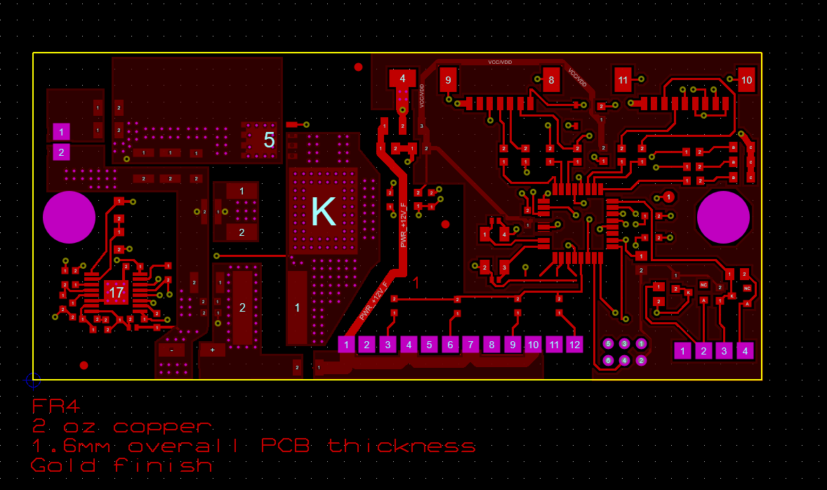
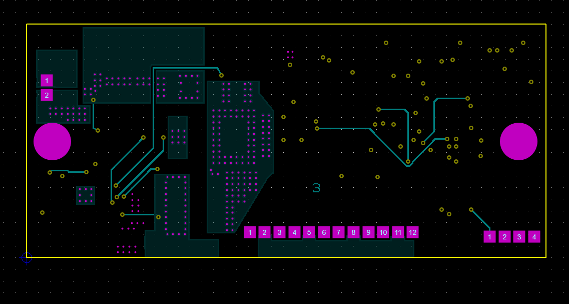
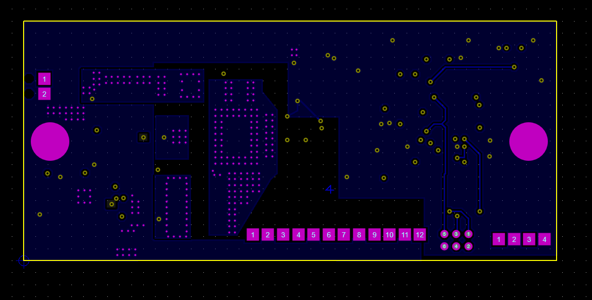
Layout all layers

Top copper

Inner layer 1

Inner layer 2

Bottom layer

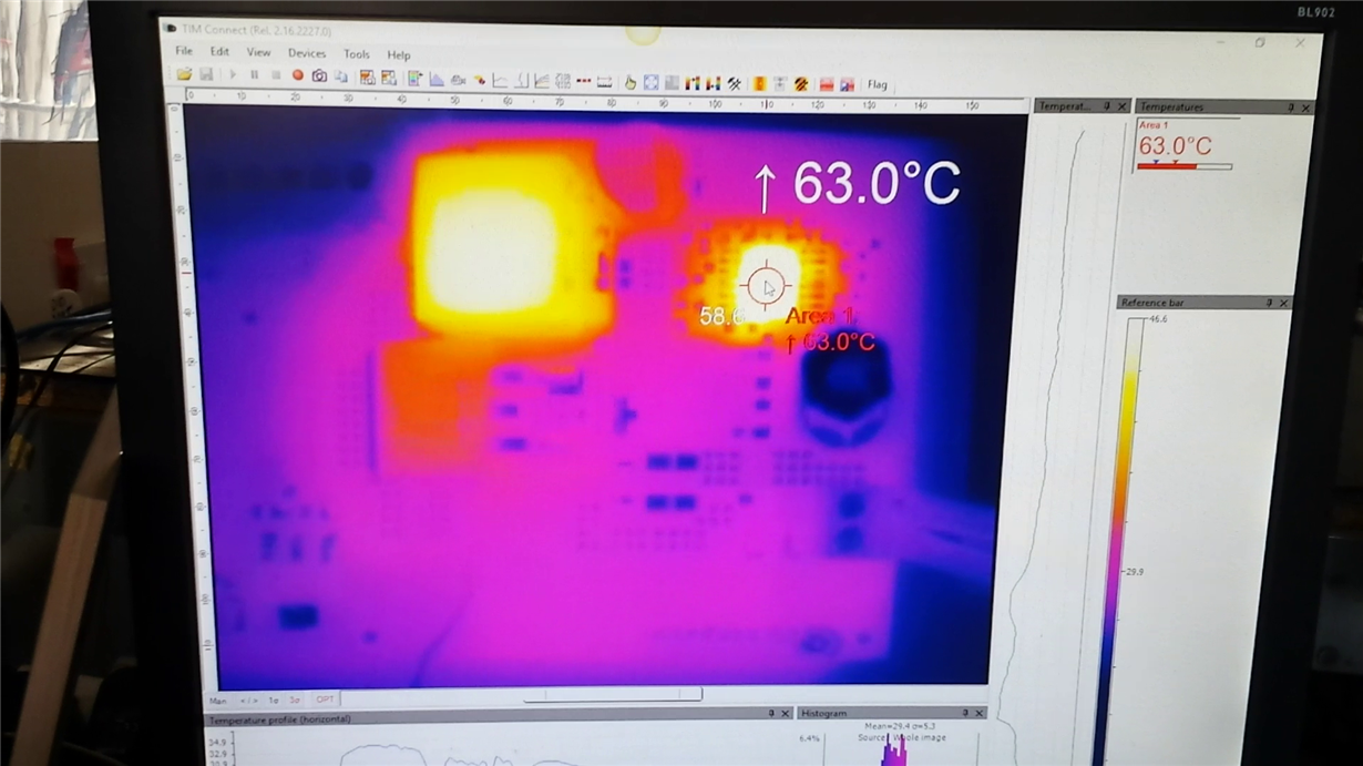
Thermal Camera image just before LM5088 failure. Cursor showing LM5088 at 34 degrees C. The inductor is at 47.4 degrees C.

Thermal Camera image just after LM5088 failure

  • Hello Jerome,

    Looks like you are switching at a frequency of ~500kHz which yield gate drive currents of 24mA.  with a Vin of 48V the power dissipation of the Device will be greater than a Watt of power.  I suggest lowering the switching frequency to ~300kHz. 

    Another idea is to supply a voltage to the VCC externally through a Diode to reduce the power dissipation in the device.

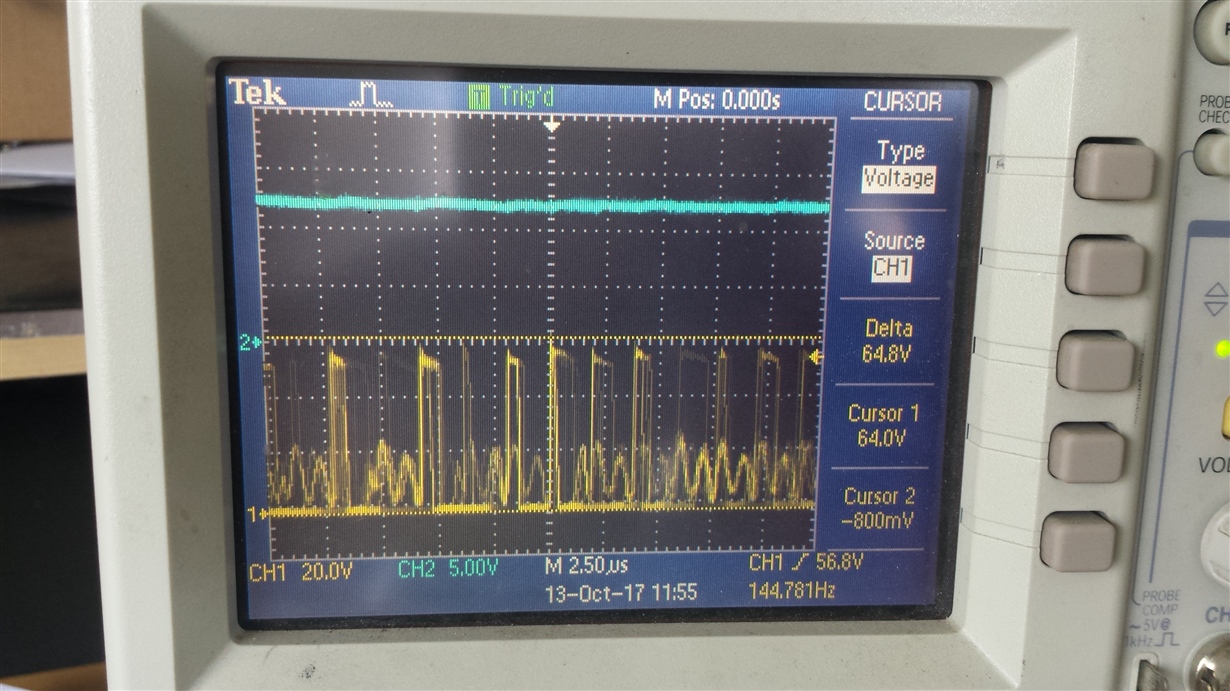
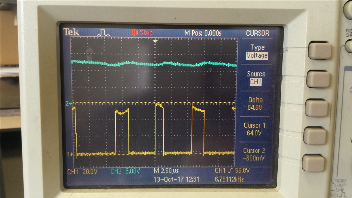
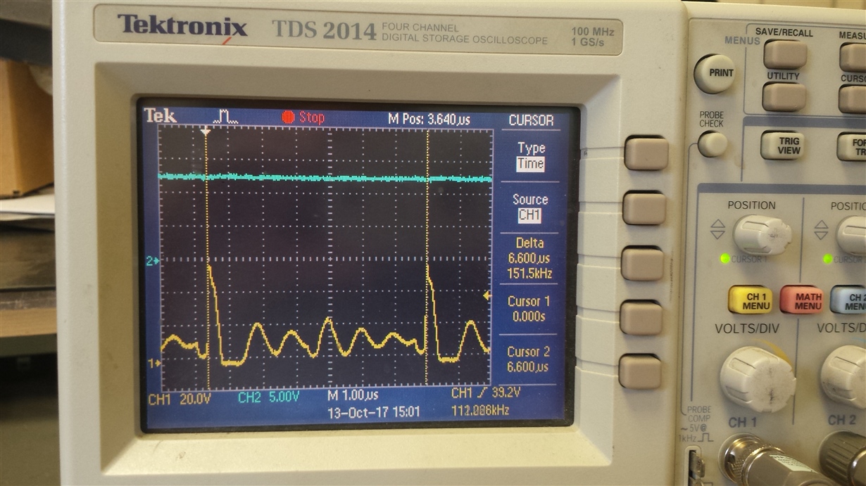
    Can you please take some scope shots of the Switch node before failure?  Want to make sure your design is stable.  Thanks.

    David.

  • So do you think this is purely a over heating issue?
    If so why is that? And does the LM5088 not shut down in the case of over temperatures rather than sustain permanent damage? 

    I'm just working on getting better scope images.

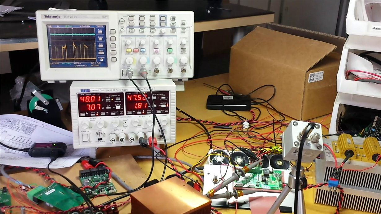
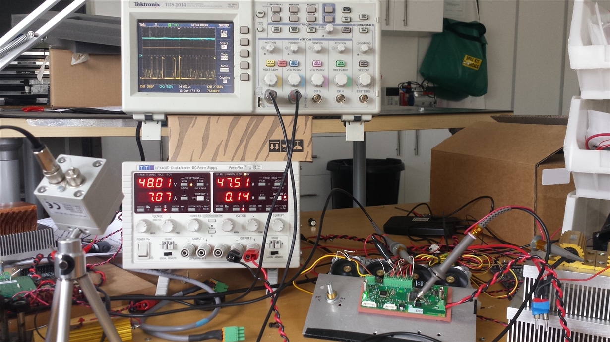
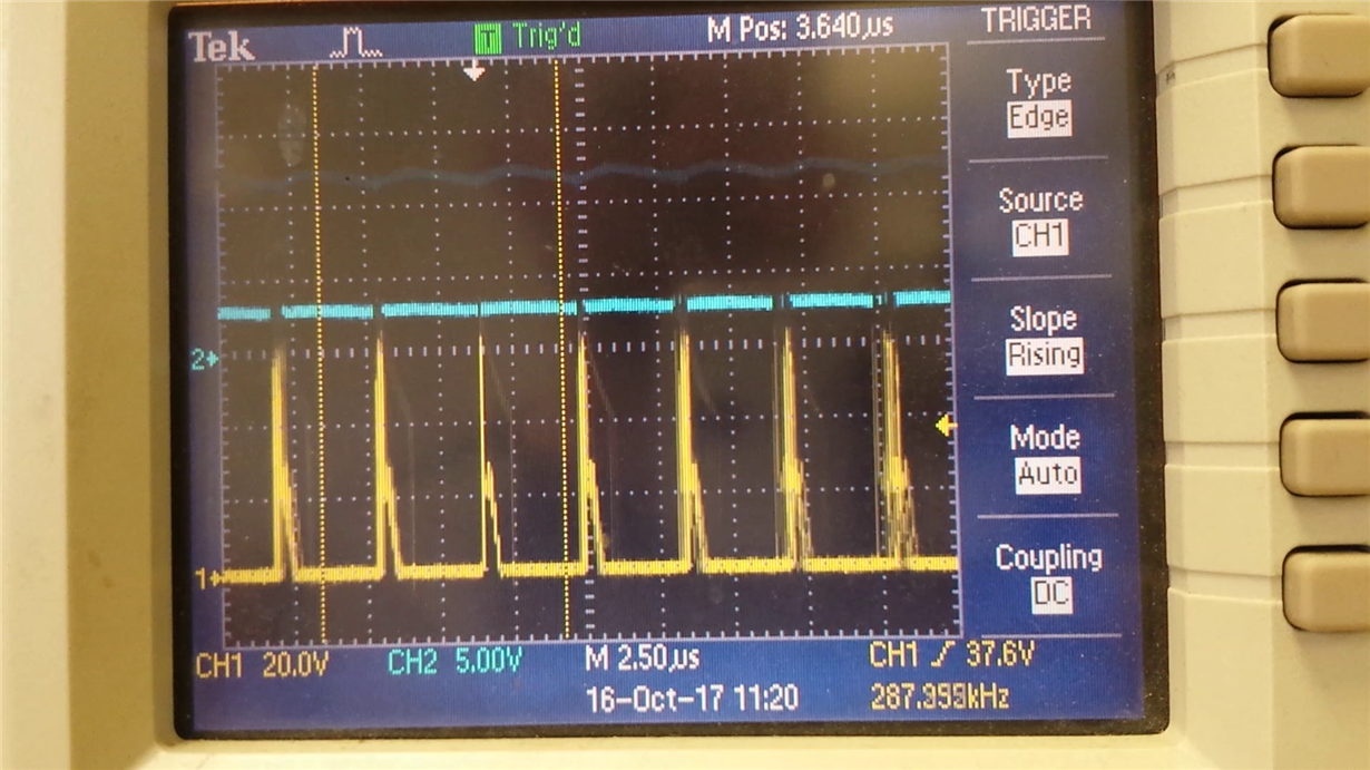
    Here is one I've captured while doing the previous test, it's not great quality.

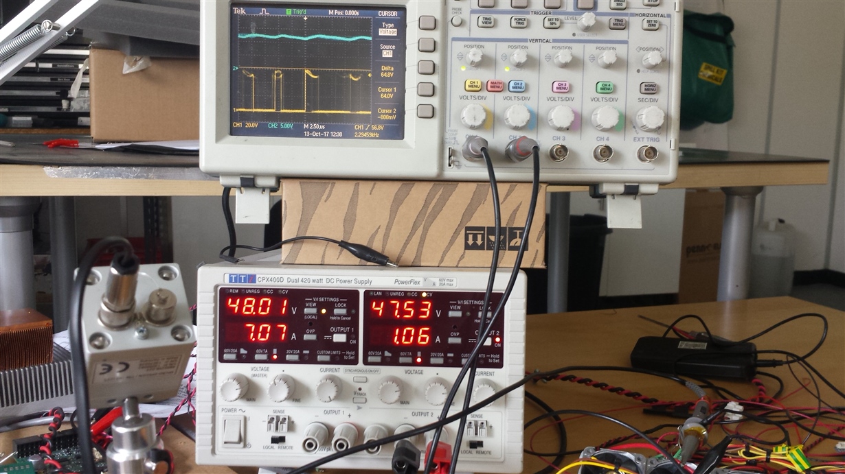
    I've made a video of the last test, is there a way I can send this to you?


    This was just before LM5088-1 failure 
    I'll work on getting a better picture 

    Here we show the four fans running at minimum 

    Instead of the PWM fans, here is a purely resistive 3R3 Load. But as mentioned, increasing this purely resistive load, (reducing resistance to 1R65), also causes LML5088 failure
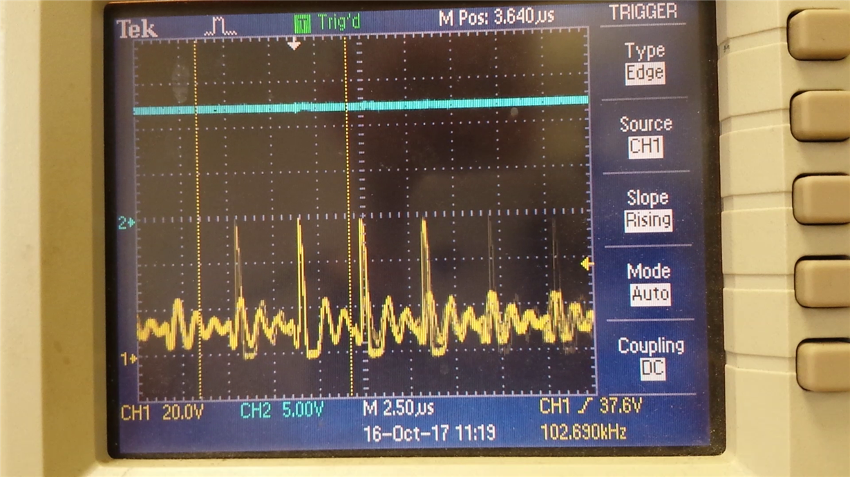
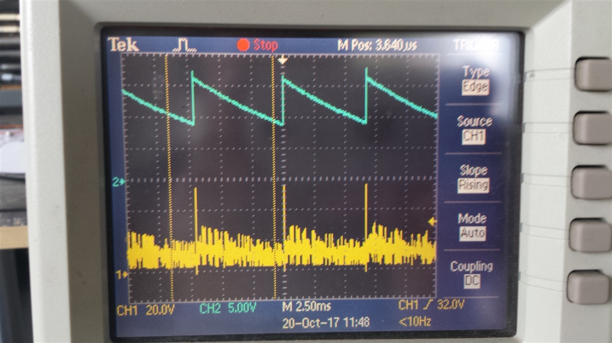
    Here's HG with no load

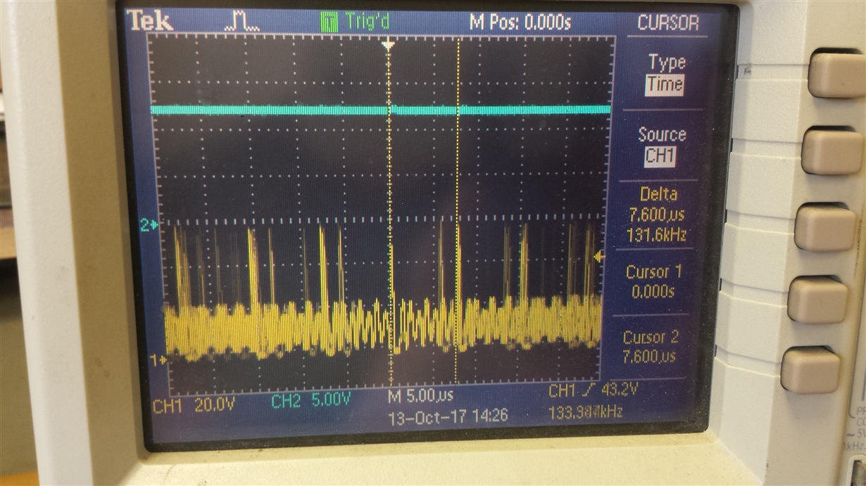
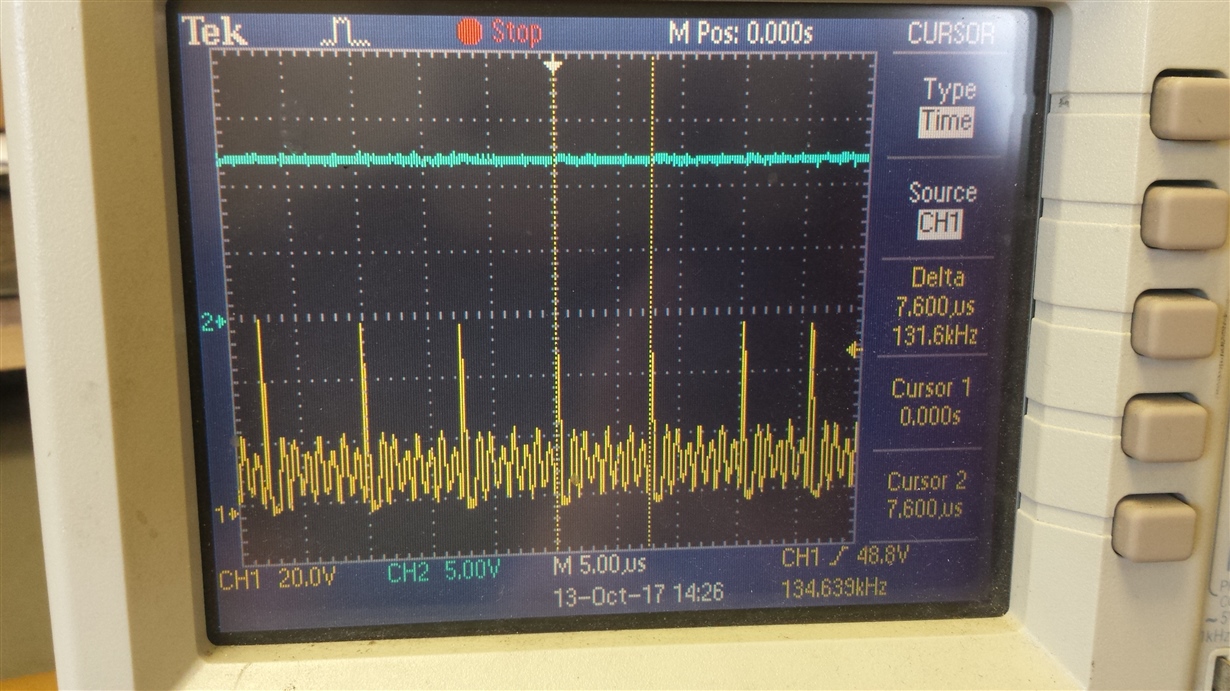
    Here I've changed RRT to be 20K instead of 10K7 (this should be 300Khz?)

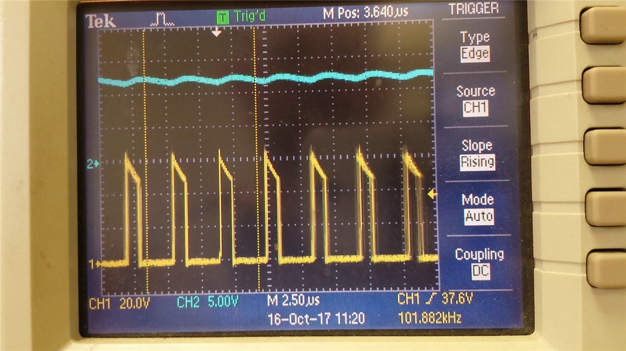
  • The loop looks unstable. Looking at your schematic, it appears you only have 22uF of Cout? I would suggest you increase this for the finished design. But taking things one step at a time and leaving Cout at 22uF, please Change R5 to 5k and C3 to 4.7nF. The Switch node should not jitter. Any instability can cause failure.

    Hope this helps?

    David.
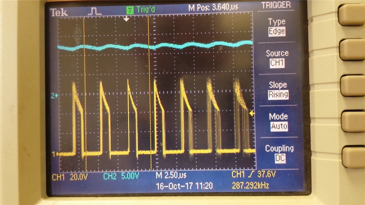
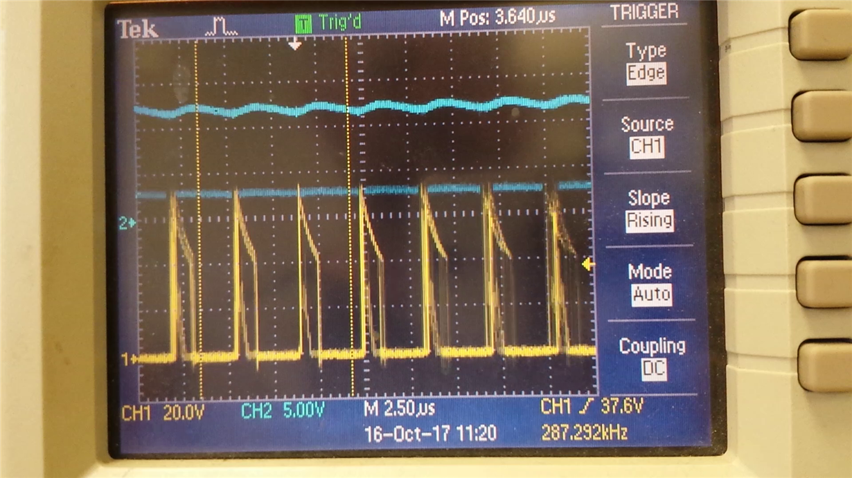
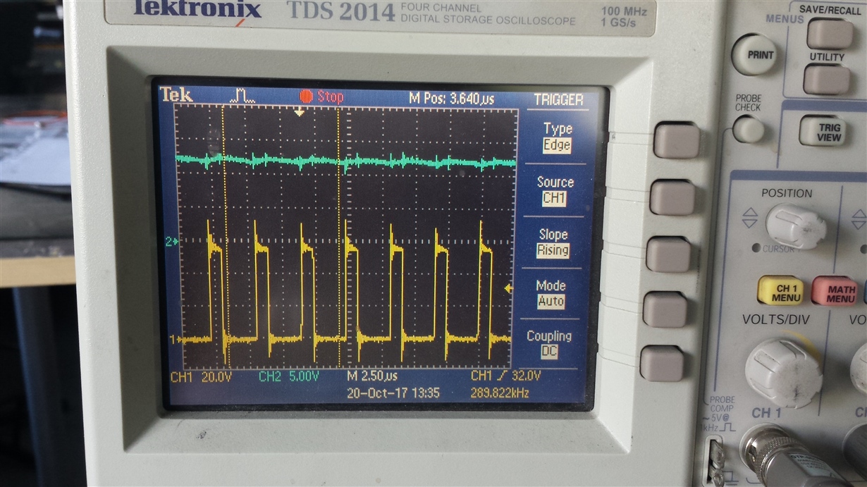
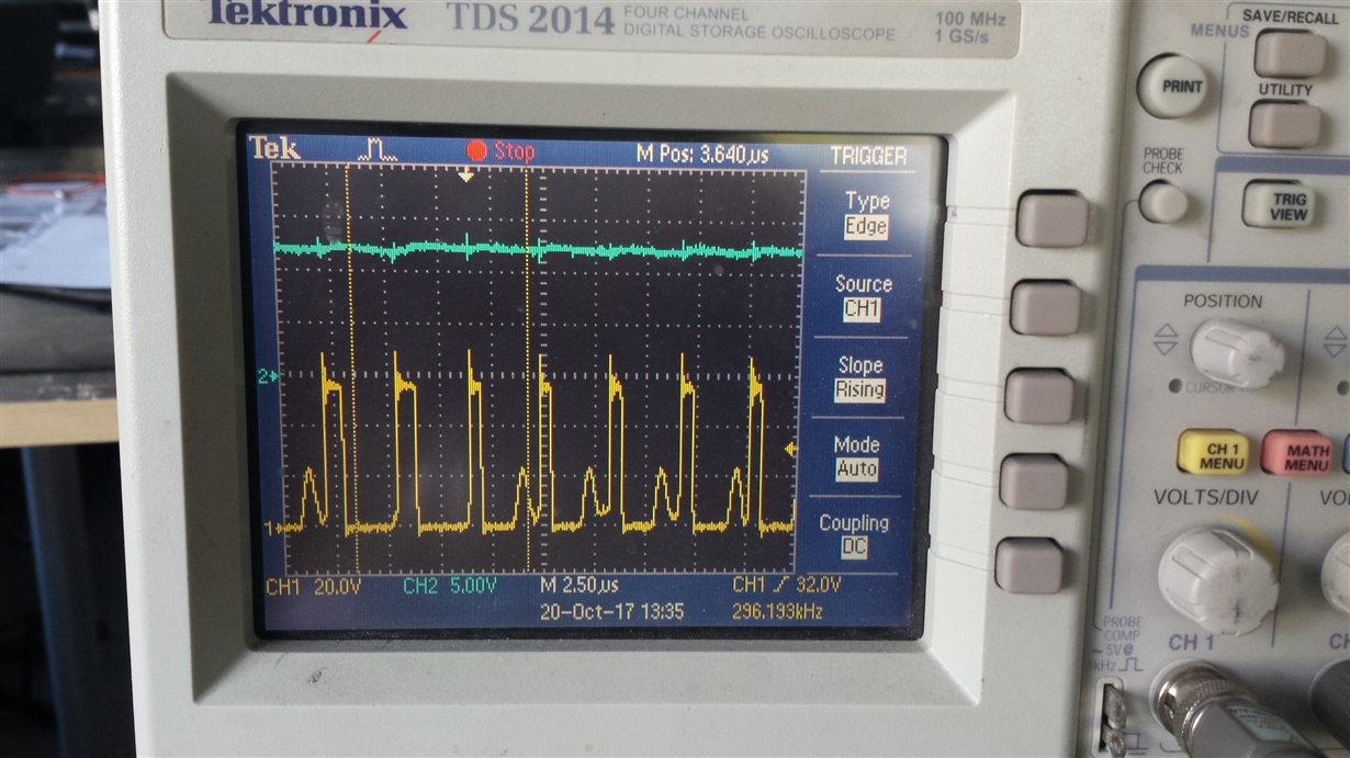
  • Hi, i've made the change of these two components as shown in below scope images, but unfortunately the LM5088 now seems to die quicker, (I'm getting through quite a lot of these devices now).

    I could send you a video of the scope when the LM5088 fails if it helps?

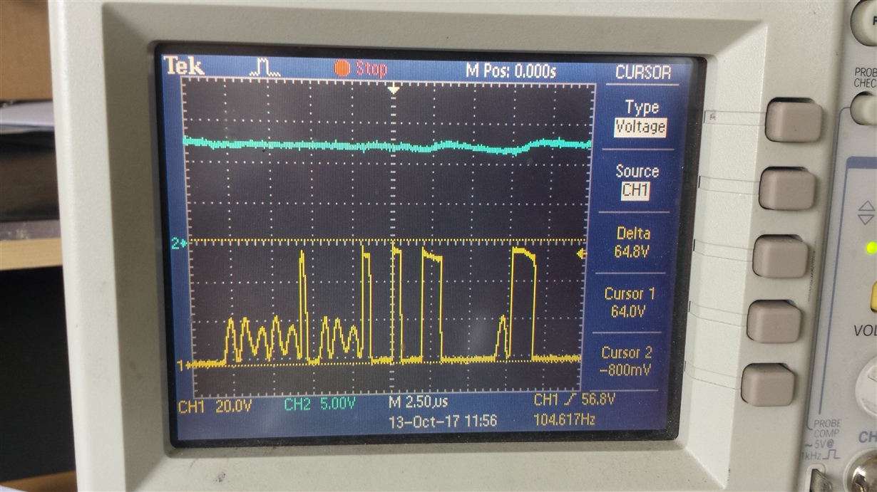
    Here I'm going to include screenshots of the point at which the device fails from minimal load to 3R3 and then 1R65 resistive loads.

    When the 1R65 load is applied the device becomes terminally damaged within a second.


    Thank you for your help with this.


    Minimal load.

    3R3 Ohm load

    1R65 Ohm load

    LM5088 beginning to fail within seconds

    LM5088 continuing to fail (a few frames later)

    LM5088 failed completely


  • Hi, any more thoughts on this issue?
    Thanks
  • So as you can see that seemed to make the LM5088 more prone to failure. Is there any idea as to why these LM5088's are failing?
    Thanks

  • The Scope Shots show that the loop is still unstable, even though you triggered and stopped on a stable region?  I still think you have a stability issue.


    Can you obtain a large Electrolytic capacitor with a high ESR (say 0.5ohm) and place it at the input.  I am suspecting you have long leads adding parasitic inductance to the input that may need to be damped.


    use a 100uF or so.


    Hope this helps?


    David.

  • Hi, apologies the test circuit didn't match the schematic (although it does match the Webench output).
    Where it showed the input capacitors as 2.2uf + 2.2uf + 1uf it was only 1uf. (this matches the Webench output)

    When adding the 100uf electrolytic the output became less stable if power was removed then replaced.
    This is what happened

    Noticing this I removed all input capacitors
    This resulted in the LM5088 physically exploding with the application of input voltage.

    And so I replaced the 1uf along with the two 2.2uf capacitors and the LM5088 has not failed since, so far.

    1R65 load

    3R load

    minimal load


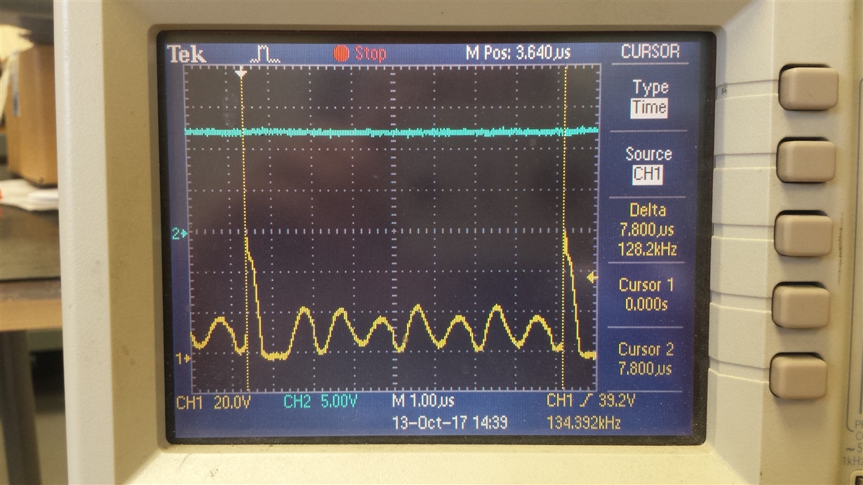
    Should the minimal load gate waveform look like that?
    Should it be a clean square wave on there instead of what you can see here?

    Regarding the output capacitance. I notice Webench keeps changing its design. 
    If I go through the same procedure now, it shows much larger output capacitance than it showed originally.
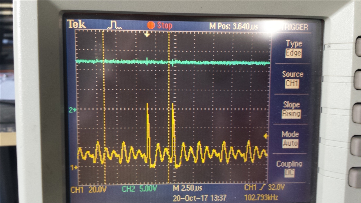
     

  • I tested with the input capacitance of 1uf + 1uf and the LM5088 didn't fail immediately.

    To help me understand what's happening, why would the LM5088 fail with 1uf input capacitance but not fail immediately with 1uf + 1uf input capacitance?

    Thank you for your thoughts on this
  • Taking into account the DC bias effects of the input ceramic capacitor, I think 1uF is undersized this will cause a large ripple voltage to be present at Vin.   From your switch node waveforms, you can see the huge voltage slope when the Switch is high.  Also 1uF capacitor may not have enough RMS ripple current capability.  A good approximation to use is Iout/2.  Which in your case is an RMS ripple current rating requirement of 5A.  Under sizing this capacitor from a value perspective and RMS ripple current rating perspective will yield poor performance, from a thermal perspective and from a operational perspective.

    PS: Looking at the gate voltage at light loads, looks normal to me.

    Hope this helps?

    David.