This is just an interesting circuit I heard about and can be helpful for some battery-powered applications. Here are some various schematics with some details about the specific ones. Note: the various pictures are uploaded from Wikipedia Commons and are done by "Rowland - Own work, CC BY-SA 3.0, https://commons.wikimedia.org/w/index.php?curid=31834817."
The coil consists of a standard ferrite toroid core with two windings of 20 turns each using 0.15 mm (0.006 inch) diameter wire (38 swg) (34-35 AWG). The circuit can utilize an input voltage down to about 0.35 V and can run for weeks using a 1.5 V LR6/AA. The battery voltage is usually 1.5 V. The resistor is ~1 kΩ, 1/4 W. The transistor could be a 2N3904, BC547B, 2SC2500, BC337, 2N2222, 2N4401 or other NPN. Vceo= 30 V, P= 0.625 W. A white light-emitting diode with Vf= 3.2 V might be used. For an isolated output for say a substitute for a 9V battery or a rail splitter a third and fourth winding could be added to the core. The waveform of an operating joule thief, showing a 30% duty cycle at approximately 40 kHz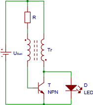
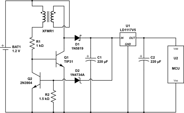
This is one with regulated output voltage.

This the final one and can be used to run something like a microcontroller off of a single AA battery. For an easily adjustable output voltage on the closed loop part of it, something like the TL431 adjustable voltage reference could be used in place of the Zener. Note: for a voltage output higher than ~7 volts a diode should be put with the anode at ground and the cathode at the base of Q1.