This thread has been locked.

If you have a related question, please click the "Ask a related question" button in the top right corner. The newly created question will be automatically linked to this question.

LMR23630: Inductor selection for highest light load efficiency

Part Number: LMR23630

Hello TI,

1. Does TI WEBENCH also account for the AC losses when calculating the inductor power dissipation?

2. Selecting an inductor with lowest DC resistance will give the best efficiency. What other parameters of the inductor should be taken into consideration when considering the light load efficiency? We want the switching convertor to consume as little current as possible under light loads.

3. I'm trying to find a suitable inductor for our design with the LMR23630A (400 kHz) which will power a GSM modem. WEBENCH suggests the Coiltronics XAL7030-822. An application note from Würth Elektronik mentions that for switching frequencies between 100kHz and 1000 kHz it is better to use ferrite and to use iron powder for less than 100 kHz. How true is this recommendation? Is it still advisable to go ahead with iron powder or other composite cores for the 400 kHz LMR23630A? What disadvantages other than cost would you mention with regard to inductors that have cores other than ferrite?

4. The LMR23630A should also turn on if the EN pin is supplied with a 1.8V, right? The datasheet mentions a threshold of 1.6V.

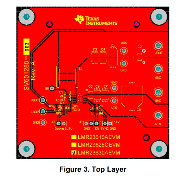
5. Can the ground pour on the top plane extend all over the PCB? The second layer is a complete ground plane. The datasheet mentions a 'localized' ground plane on the top, can you elaborate on this?

  • Pradeep,

    We are gathering info to answer your questions. We will get back to you shortly.

    -Sam
  • Pradeep ,

    Please find below our response :

    1. No Webench doesn't account for the AC losses across the inductor .

    2. Choose Inductor which has lowest DCR possible as well as  saturation current highe than the current limit of the device . On the  core side , powered iron composite inductors, that you understand this a ‘soft’ saturation and the L will still be there at a good level well into saturation unlike and opposite the behavior of a ferrite core inductor, where the L would fall off fast and move toward zero very fast once you saturate the core.  XAL uses  powered iron composite core .

    3. Composite iron core as stated above .

    4.  

    Anything higher than 1.7V should work . 

    5. You can use top layer for power related routing , INNER layer 1 as GND , INNER layer 2 for signal connections , Bottom layer as much GND as possible . 

    --Ambreesh 

  • Hello Ambreesh,

    first off, thanks a lot for the detailed answers. Much appreciated!

    I'm sorry if I wasn't clear enough in my previous post. 

    WEBENCH suggests the Coiltronics XAL7030-822. An application note from Würth Elektronik mentions that for switching frequencies between 100kHz and 1000 kHz it is better to use ferrite and to use iron powder for less than 100 kHz. How true is this recommendation? Is it still advisable to go ahead with iron powder or other composite cores for the 400 kHz LMR23630A?

    Would you be able to shed light on why Würth Elektronik recommends to use ferrite for >100kHz switching frequencies inspite of the disadvantages?

    You would still recommend going with the XAL with composite iron core even if the switching frequency is 400 kHz?

    Please correct me if I'm wrong, are carbonyl iron cores different to composite iron cores? I'm also looking at the Bourns SRP1038 series.

    Regarding the layer routing, well the issue if we have chosen a different stack up.

    Layer 1 : Signal + Ground pour

    Layer 2 : Complete ground

    Layer 3 : Multiple Vccs (3.3V digital 3.3V analog 1.8V polygons and the Vin 12V trace)

    Layer 4 : Signals + Ground pour

    My question to be more exact is, does this 'localized' ground plane recommended in the TI datasheet have to be split from the rest of the ground pour on the top plane and connected to the inner layer ground with vias? 

    I'm not really comfortable with splitting the ground pour on the top layer unnecessarily, the vias should redirect the return currents to the inner GND layer through the vias placed close to the capacitors right?

    Once again thanks for your time!

  • Pradeep ,

    The inherent high resistivity of “soft ferrite cores” minimizes eddy current losses and the inherent distributed air gaps of “iron powder cores” minimize winding losses. The two can be married as a composite core in order to exploit each materials inherent advantage while minimizing each materials short falls .( Also powdered cores typically have significantly higher core losses than ferrite cores.)

    Composite cores which are used in inductors like XAL7030 can provide a fine balance between winding and  core losses . We have used XAL series in many application  and have seen no issues .

    I dont know about cabonyl iron core .

    As far as GND plane is corned , you dont  need to split the GND plane . The only thing you need to take care of is the fact that the input and oputput loop is as small as possible ie High frequency bypass capacitor should be place as close as possible to VIN pin and PGND and same goes for output loop  .

    ----Ambreesh 

  • Thank you for the extremely detailed answer Ambreesh!