This thread has been locked.

If you have a related question, please click the "Ask a related question" button in the top right corner. The newly created question will be automatically linked to this question.

LM26480: Feedback is not stable

Part Number: LM26480

Hi,

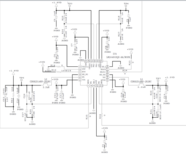
I created a circuit with the device of LM26480.
And now, I am evaluating its behavior.
I attach the circuit diagram, but the output voltage of 1.5V is oscillating.
I confirmed the SWpin, but the switching is swinging up and down in a continuous state.
I believe that there is a problem with feedback stability.

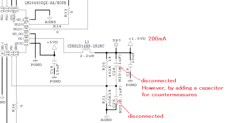
As a countermeasure, a ceramic capacitor was connected in parallel to the upper side of the feedback resistor.
I will attach the result.
Adding 120pF seems to have an effect, but there is no change by increasing the capacity of the capacitor any more.

I want to ask you a question.
Is there a way to reduce the fluctuation of the output voltage other than adding a capacitor above the feedback resistor?

(Additional Information)
Capacitors are not connected in parallel to the feedback resistor of the circuit diagram in the first place.
An output voltage of 1.5V supplies a current of about 200mA to the load side.

Best Regards,

  • Hi,

    I have assigned your request to responsible Applications Engineer and we will get back to you as soon as possible.

    Regards,

    Murthy
  • The datasheet recommends that a 10pF capacitor is used as C1 (C28 in your design) when the output voltage is 1.5V

    120pF is the capacitor you value used, and 12*10pF = 120pF. This is an order of magnitude higher than the recommendation and these feed-forward capacitor selections are very specific in Table 5 of the datasheet. Generally speaking, feed-forward capacitors are very small (1-20pF).

    Please test again with the recommended capacitance of 10pF.

    If this does not help, here are a few other things you might want to test:

    • Does the same issue occur on DCDC1 of your PCB?
    • Does the issue still occur when DCDC2 is fully loaded at 1.5A?
    • Is the feedback signal (FB2) noisy? Is the GND connection at any of the pins noisy?

  • One final suggestion would take some time, but if none of the other suggestions work then this option should be tested:

    Request a sample of Orderable Part # "LM26480QSQ-CF/NOPB" and re-test.


    Can you provide us the top-side marking on the LM26480 chip that is failing in your design?
    It should end with "26480AA" and have 7 alpha-numeric values before it.
  • I really appreciate your answer.
    Regarding the layout, a place where the signal system is influenced by noise is found, and there is a high possibility that this symptom is affected.
    Therefore, I will take countermeasures from this content.
  • Before you look for noise sources all over the PCB (it will take some time),

    Can you please re-run your previous tests at:

    • No load
    • Full load (>1 A)

    and take scope shots recording your results? The C28 feed-forward cap can be NC when you re-run the tests.

    This will be very helpful. Thanks!

  • Thank you for your reply.

    In the circuit I created, I can not cut the actual load (200 mA), so I can not test with No load. After that, the output voltage was measured in a state where a dummy load was added and a load of 1.5 A could be supplied, but the symptoms were further deteriorated.

    For the value of C28, it is not implemented or measured at 10pF, but it does not affect the symptoms at all.

    I made AGND as the ground of the signal system in creating the layout.
    However, I think that the method of making AGND was bad.
    Therefore, I will review the contents.

    Best Regards,
  • Please explain how "the symptoms were further deteriorated" when a load of 1.5 A was applied.

    • Did the instability get worse, resulting in a larger ripple?
    • Did the ripple get so high that the output voltage clamped at VIN (or went down to GND)?

    This will be important info when we try to test this issue in the lab at TI.

  • Can you provide us the top-side marking on the LM26480 chip that is failing in your design?
    It should end with "26480AA" and have 7 alpha-numeric values before it.