This thread has been locked.

If you have a related question, please click the "Ask a related question" button in the top right corner. The newly created question will be automatically linked to this question.

LM27762: Chip draws ~10x current at startup

Part Number: LM27762

I'm having an odd issue with this chip.  I've been bringing up the board piece by piece, and after adding in a second op amp utilizing the power rails created by this chip (+/- 2.5V), it began to have a strange start up behavior.  Upon applying power to the board (5V), the LM27762 produces the appropriate rails, but the current draw on the 5V supply is around 200mA and the switching capacitor (C1) has a 2Mhz square wave on it.  After a variable amount of time, usually around a minute, the current draw on the 5V supply drops to 20mA or less (i.e. where I expect it to be), and the switching cap shows short 2Mhz bursts at a frequency of around 46Khz.  

This points to some startup instability, but I'm not sure where to look.  I used Webench to get the discrete values for this design, and tried to keep the layout as close to the recommended design as I could.

Suggestions?

  • Adam,

    Would you be able to send a picture of your schematic and layout so I can take a look at it?

    It might also be helpful to measure the current coming out of the LM27762 to see what kind of a load the op-amp is putting on the LM27762.

    Thank you,
    Nick
  • Sure, I've attached screen shots of both.  If you need more detail on either, please let me know.  I found that the current draw was coming from the op-amp as expected, and I think it has to do with noise on the supplies due to the C1 switching cap interacting with an unused gate.  I tied the inputs of the unused gate together and it seems to have stopped the startup current problem, but I still see significant switching noise on my output due to the opamp amplifying the noise on the supply.  While I wait for your response, I'm going to try some standard techniques to see if it can be solved without changing the layout.

    Schematic:

    Layout (2 layer board):


    Top and bottom planes are both AGND

  • Adam,

    I am glad you were able to figure out the current startup issue. I would check the datasheet of the op-amp to see what is recommended for unused pins.

    As for the layout I think you might be able to improve your noise performance by improving your grounding. Wider traces on C40, C42, and the thermal pad would help. More importantly the input cap C38 should have a very close connection to the GND pin. With your current layout the input cap's closest connection to GND is around the other external components and through the thin traces between R41, C42, and R43.

    If you have an EVM you can use that to see if it solves your issue, as the EVM will have a very good layout and BOM.

    If you want to send any scope shots of your noise I would be happy to take a look at those as well.

    Thanks,
    Nick
  • I ended up grabbing an EVM for comparison purposes.  I modified it by changing R1-R4 to set the output voltages I need (+/- 2.5V).

    FYI: The EVM user's guide contradicts the Datasheet by stating the -Vout formula to be -1.2V x (R3+R4)/R4.  It should actually be -1.22V as the multiplier.

    I also modified my board to improve the Vin Cap's ground connection, and changed my other capacitors values to match the EVM.  In both cases there is a negligable load on the +/-2.5V supplies.

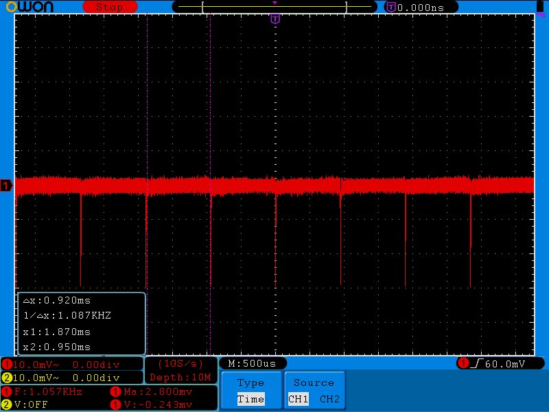
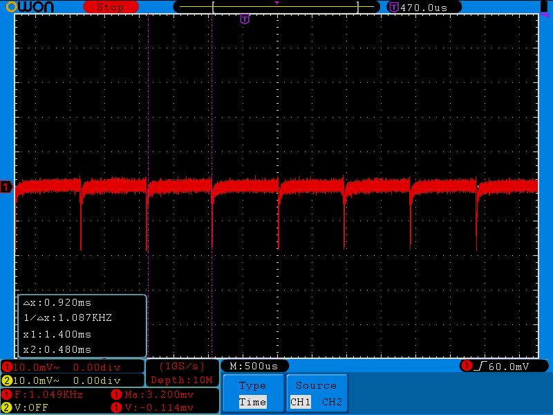
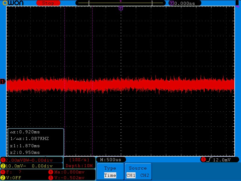
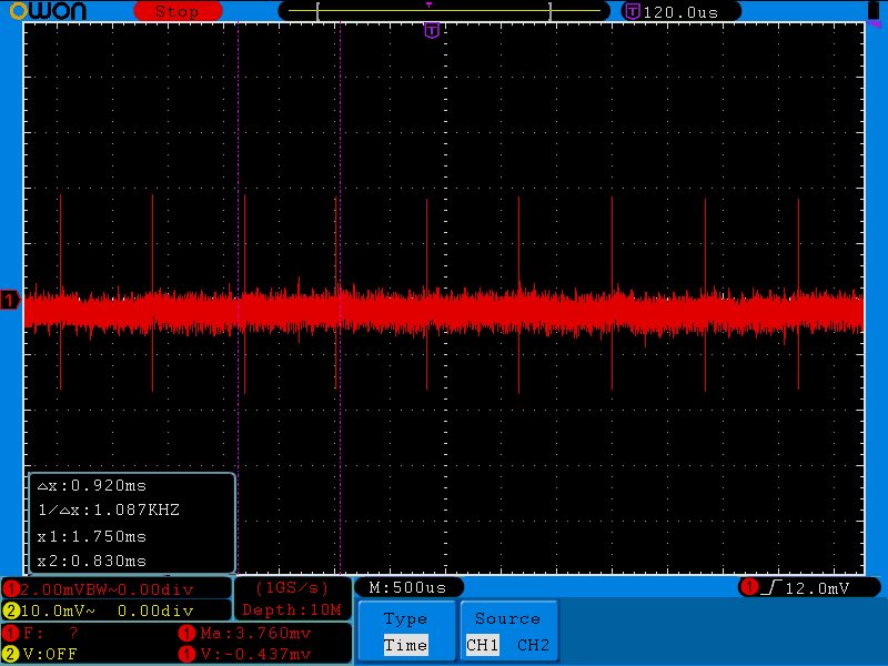
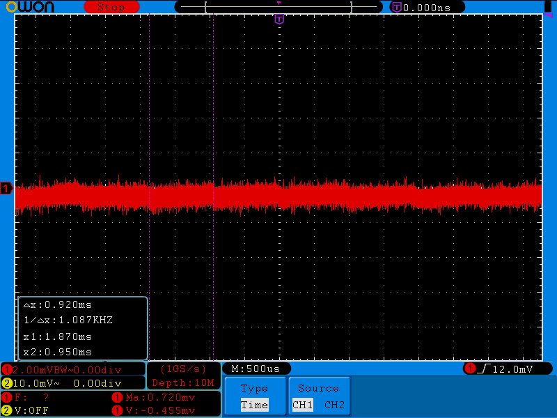
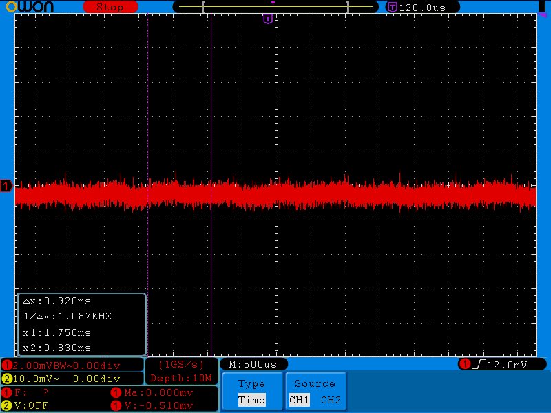
    Here are the results, :

    EVM, VIN:

    My VIN:

    The spikes on my VIN are likely reduced because I scoped the opposite side of an inductor.  This still seems like a lot of noise to inject back into the input.

    EVM +2.5V:

    My +2.5V:

    Note the switching spikes carrying though.

    EVM -2.5V:

    My -2.5V:

    A little noisier, but not too bad.

    Is the noise on the Vin side normal?

    I'm going to see if I can get the spikes on the +2.5V line to die down a bit, but I'm not sure how much I'll accomplish without a board spin that addresses the ground issues you identified.  Are there any other suggestions?

  • Hi Adam,

    These spikes are normal. Most likely, you just need to measure it with a better setup including a low inductance probe as shown here: www.ti.com/.../slva494a.pdf and training.ti.com/measuring-vout-ripple-dcdc-converters

    A ferrite bead is commonly used to block any high frequency content that is actually present.