This thread has been locked.

If you have a related question, please click the "Ask a related question" button in the top right corner. The newly created question will be automatically linked to this question.

TPS60402: https://e2e.ti.com/blogs_/archives/b/precisionhub/archive/2015/03/10/2-wire-4-20ma-sensor-transmitters-background-and-common-issues-part-5

Part Number: TPS60402
Other Parts Discussed in Thread: XTR116,

Dear sir,

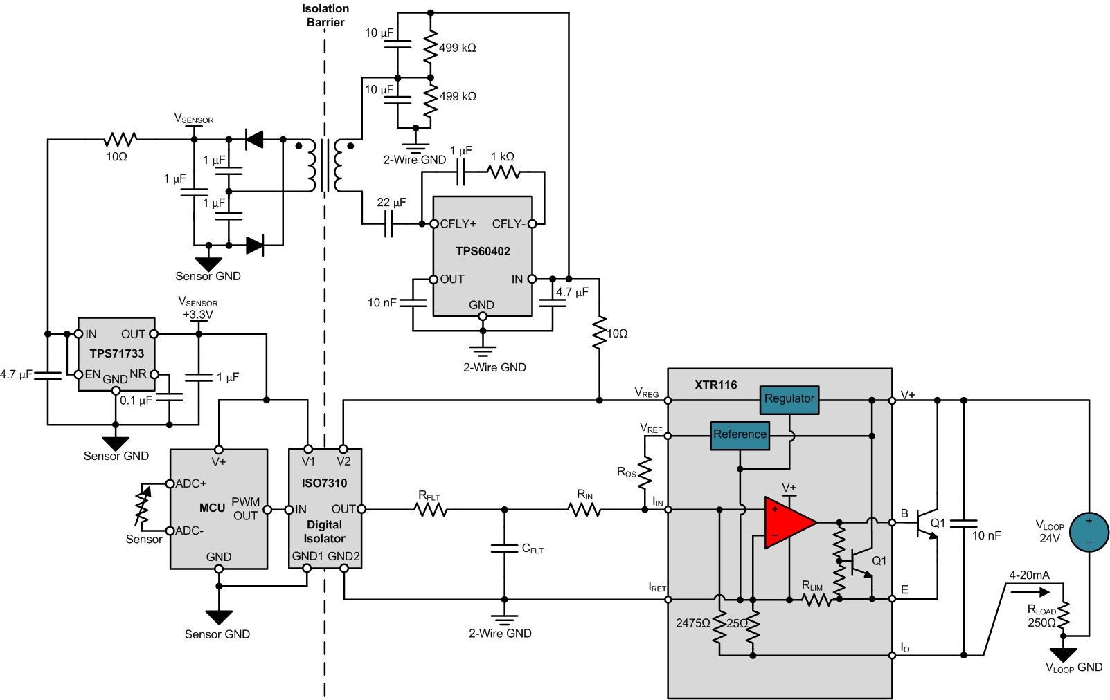
We built the circuit as Figure 4: Input-sensor-isolated 2-wire transmitter from following link

e2e.ti.com/.../2-wire-4-20ma-sensor-transmitters-background-and-common-issues-part-5

But we are facing following issue.

when we check 4 to 20 mA  output, we find 12 mA by default instead of 4 mA.

But when we disconnect input supply of TPS60402, default output is 4 mA. But we need this output by supplying to TPS60402.

How to fix this issue ?

following is the sch. for reference.

regards,

shashikant 


  • Hello,

    It sounds like you're returning too much current back to the transmitter which is preventing you from reaching the desired minimum 4mA level.

    What type of load do you have on the output of the LDO on the secondary side?  You won't be able to return more than ~3.5mA back into the "IRET" pin of the XTR116 while being able to achieve the 4mA zero-scale level.

  • Also, you may find the attached TI reference design useful which utilizes a very similar circuit: www.ti.com/.../TIDA-00189
  • Dear sir,

    Thanks for reply.

    On secondary side, to LDO, we connect low power pic microcontroller and two low power ics like TS556 and CD4538. Input for circuit is variable capacitance.

    Ground of secondary side and primary side is isolated. as per diagram. So who is adding loop current in path of "IRET"?

    Kindly request to suggest that how to fix this issue.

    regards

    shashikant
  • Hello,

    The current through the transformer on the primary side returns to the IRET pin, along with the quiescent current of the TPS60402, the currents of the digital isolator and any other circuitry powered from the VREG output of the XTR116.

    Depending on how you're operating the TPS60402 and what type of efficiency it's achieving you'll likely not be able to consume more than 1-2mA on the secondary side.

  • Dear sir,

    Lastly we have design such transmitter without isolation. In that design we supply pic mcu, ICS TS556 and CD4538 by XTR116 supply.
    In that case such problem is not there.

    Default current is 4 ma and as per capacitance input change it increase up to 20 ma.
    It is working fine.

    But when it is install on field , readings start to fluctuate. So we decide to provide isolation.

    So pl tell how to fix this issue.

    regards,

    shashikant
  • Hello Shashikant,

    I agree with Collin, the fact that the issue goes away when you disconnect the TPS60402 almost certainly means that the input circuitry is consuming too much current. If the circuit continues to perform as expected above 12mA then you can be confident this is the case. Without knowing exactly how everything is configured it is difficult to give a simple way to fix the problem, but I would suggest re-evaluating your input configuration.

    Given that the circuit performs as expected without isolation, your problem likely lies in the configuration of your digital isolator and TPS60402. The digital isolator alone can consume up to 4.2mA on the Vcc2 side and 1.3mA on the Vcc1 side if running at the maximum data rate. You may need to decrease the frequency of your PWM signal. I'm not sure how the CD4538BC is being operated in your circuit, but it also outputs about 1mA on a 5V supply and everything on the secondary side will be reflected back to Vreg through the transformer (which I'm assuming is 1:1).
  • Dear sir,

    Thanks for reply.

    I have checked the PWM frequency is 555 khz maximum. It goes on reducing for different combination of input capacitance of sensor.
    Even PWM frequency is reduced same current is there, 12 mA by default instead of 4 mA.

    If I remove Digital Isolator ic ISO 7310 then also current is 11 mA.

    We have design low power dc to dc converter using TPS60402 , by taking reference from TI reference design TIDA00349

    Pl. suggest how to reduce current adding in loop current in path of "IRET" of XTR116

    regards

    shashikant
  • Dear sir,

    By mistake I have unsubscribe the email notifications for this thread. Pl. reactivate it.

    Thanks
    regards,
    shashikant
  • Hi Shashikant,

    Please provide a detailed schematic of everything in this system. I understand it is similar to what has been posted above but I'd like to see how your are actually implementing this to determine where the issue is. You may also try measuring the current in other places to determine what is consuming so much current.

    With regards to the email notifications I have no control over that, you have to re-subscribe yourself.
  • Dear sir,

    Pl. find attached sch. in previous post.
    Change in sch. is microcontroller. We use PIC18LF2520.
    Pl. check the sch. and suggest the solution.
    I will also study in detail.
    Thanking you,

    shashikant jadhav
  • Dear sir,

    Do you get the sch. ? If you received , pl. provide the update on solution of issue.

    regards,
    shashikant
  • Hi Shashikant,

    Looking over the components in your system I think the most likely culprit is the PIC16F876A. This version of the device with a 20MHz oscillator like you have in your schematic consumes between 7-15mA in quiescent current. There is a 16LF version of the device that uses a 4MHz oscillator and the quiescent current for that is only 0.6-2mA. This may be a more suitable component.
  • Shashikant

    We haven't heard back from you so we assume this answered your questions. If not, post another reply below, or create a new thread if this one has timed-out.

    Thanks
    Dennis
  • Dear Zak Kaye and Dennis,

    As per your suggestion , I am trying to change the PIC16F876A to another new mcu may be PIC16LF1718 or PIC16F1618. It is low power controller running at 20 MHz. But for this I need to change firmware accordingly. So I am making it. Very soon I will back with its feedback.

    regards,

    shashikant
  • Dear Zak Kaye and Dennis,

    As per your suggestion I have changed the MCU to PIC16F1718. As per datasheet ,It is taking 2.1 mA current at 32 Mhz.
    Our controller is working on 20 Mhz. We can't lower controller frequency. We have develop the firmware for it.
    I have checked controller card current , It is 6.98 mA.
    But our overall transmitter circuit takes 12 mA instead 4 mA.
    As both grounds are isolated then how current is mixing ?

    Pl. suggest the solution for above issue.

    regards,

    shashikant.
  • Dear Zak Kaye and Dennis,

    As per your suggestion I have changed the MCU to PIC16F1718. As per datasheet ,It is taking 2.1 mA current at 32 Mhz.
    Our controller is working on 20 Mhz. We can't lower controller frequency. We have develop the firmware for it.
    I have checked controller card current , It is 6.98 mA.
    But our overall transmitter  circuit takes 12 mA instead 4 mA.
    As both grounds are isolated then how current is mixing ?

    Pl. suggest the solution for above issue.

    regards,

    shashikant.

  • Hi Shashikant,

    Even though your grounds are isolated, the power has to come from somewhere, and it ultimately comes from the onboard regulator of the XTR. So whatever current the isolated input side consumes is sourced from the regulator and must return to IRET. I made the MCU recommendation based on it being the lower power version of the one you were using, but if this is still consuming excessive current then the solution remains the same; you need to use lower power devices on your input. It may be easier for you to power the input side externally and just keep the digital isolator between the output of your MCU and the XTR input. That way you don't have to worry about how much power the input requires.
  • Shashikant

    Did this resolve your issue? If not post another reply below.

    Thanks
    Dennis
  • Dear Dennis and Zak Kaye

    Thanks for your suggestions.

    Today I have seen your suggestions. I was out of country since last 10 days.
    I will try out your suggestions and will give you its feedback soon.

    Thanking you,

    shashikant
  • Shashikant

    Did the suggestions above resolve your issue? If not, post another reply below.

    Thanks
    Dennis
  • Dear Dennis,

    I am still trying your suggestions.

    Thanking you,

    regards,
    shashikant
  • Shashikant

    I'm going to close this thread for now, but once you've evaluated the changes in your circuit, if you continue to have problems, you can reopen the thread by posting another reply.

    Thanks
    Dennis