This thread has been locked.

If you have a related question, please click the "Ask a related question" button in the top right corner. The newly created question will be automatically linked to this question.

TPS61098: Loop compensation for motor load

Part Number: TPS61098
Other Parts Discussed in Thread: TPS61089

Hi,

I am using TPS61098 to boost voltage from LiFePo4 battery (3.2V to 2.9V) to 6 volts to drive this motor: Thomas G6/02-8

The motor draws 0.5A - 1A of current

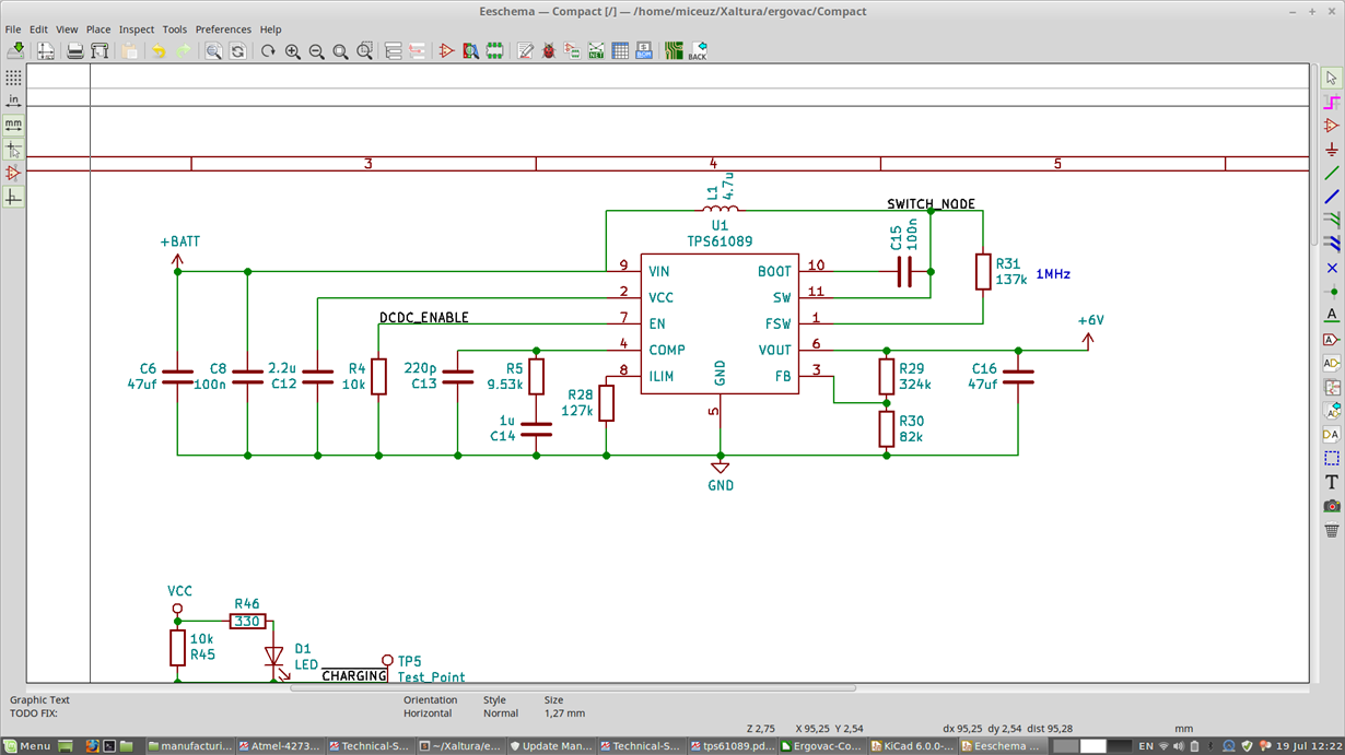
My schematics are below, the inductor I have used is COILCRAFT XAL4030-472MEB

I have used webbench tool to design the circuit, values for compensation network were R5=9.53k, C14=4.7n and C13=220p. The circuit did not start at Vin=3.2V with these values. I have experimented and found out that changing C14 to 1u made the circuit start and power the load at 3.2V down to 3.0V, but failed to power the load at Vin voltages down to 2.8V.  Then changing R5 to 1k made it work down to 2.8V. While this is fine, I feel that I am poking in the dark here.

I have made calculations based on formulas presented in the datasheet:

#Input voltage
Vin = 2.8

#Output voltage
Vout = 6

#Output capacitance
Co = 47e-6

L = 4.7e-6

#Output load resistance
Ro = 6/1

#Internal sense resistor
Rsense = 0.08

#Amplifiers transconductance
Gea = 190e-6

efficiency = 0.95

D = 1 - (Vin*efficiency)/Vout
print("Duty cycle " + str(D))

#right-half-plane-zero's frequency
Frhpz = (Ro * (1 - D)**2) / (2 * pi * L)
Fsw = 1e6
#Loop cross over frequency
#Choose to be smaller of 1/10 of fsw of 1/5 of Frhpz  
fc=min(Fsw/10, Frhpz/5)

print("Frhpz = " + str(Frhpz))
print("Fc = " + str(fc))
R5 = (2*pi*Vout*Rsense*fc*Co)/((1-D)*1.224*Gea)
print("R5 = " + str(R5))

C5 = Ro*Co/(2 * R5)
print("C5 = " + str(C5))

Resr=0.003
C6 = Resr * Co / R5
print("C6 = " + str(C6))

---------output---------------
Duty cycle 0.556666666667
Frhpz = 39.93E3
Fc = 7.987E3
R5 = 10.98E3
C5 = 12.84E-9
C6 = 12.84E-12

I have tried using these values with no luck - the dcdc converter seemed to start up and then quickly went into mode where it applies short bursts of PWM into inductor. This way the output voltage is not maintained at set 6V, but lower - around 5V.

Can someone please comment, what did I do when increasing C14 and reducing R5 drastically. Also where is the problem in the calculations? Is this related to motor being a complex load and Ro being 6V/1A is too big simplification? How do I go about properly calculating loop compensation component values? Am I safe with the values I have experimentally chosen?

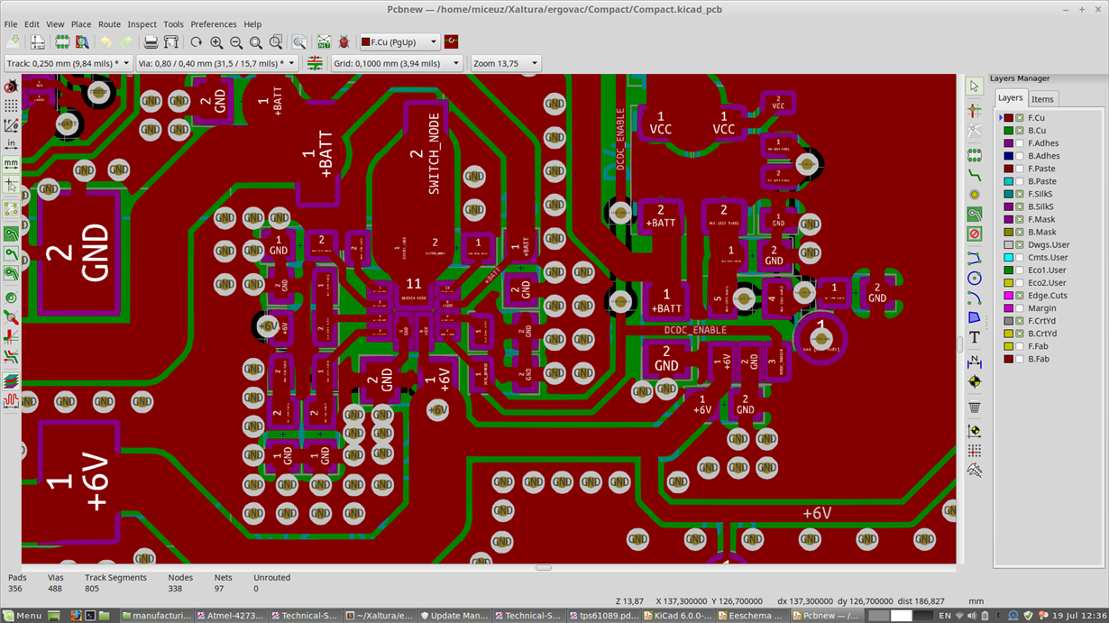
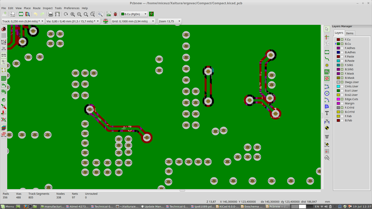
My layout is two layer:

  • Hi Albertas,

    The part number should be TPS61089? Right?
    From the schematic you show, the VCC is aslo connected to a LED? Or is this VCC an external power rail?
    Can you show me the startup wavefroms including the inductor current and SW, output voltag.
  • Yes, it is about TPS61089.

    VCC is a rail derived from 6V. There is a 5V LDO that is powering MCU and a sensor.

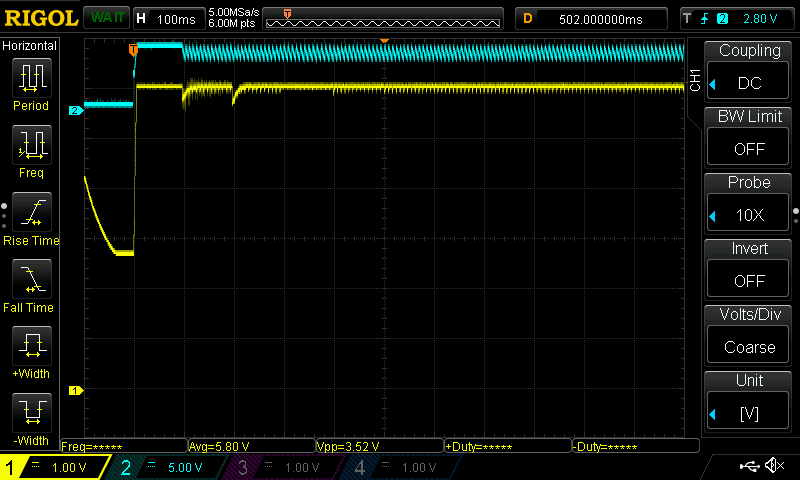
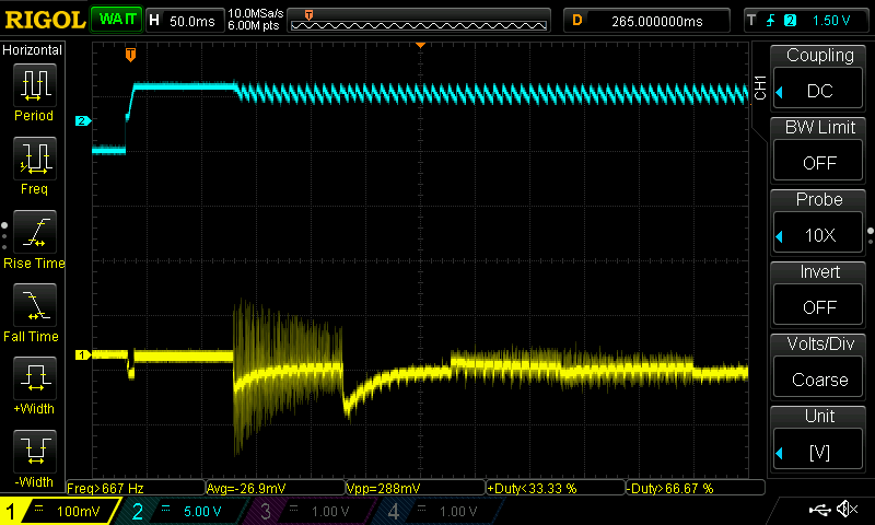
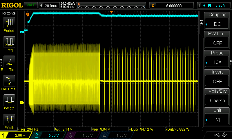
    Here output voltage during "good" startup (yellow trace):

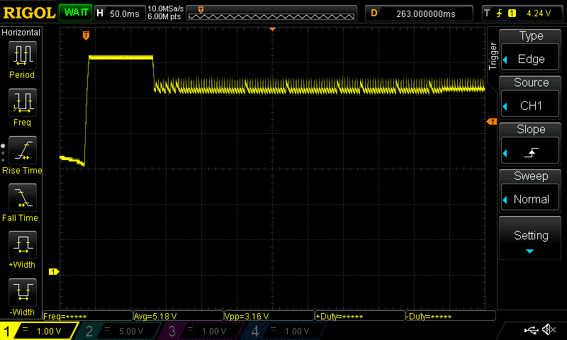
    Here is current going into Vin during "good" startup (yellow trace):

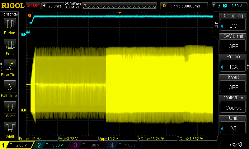
    Here is voltage on SWITCH_NODE suring good startup:

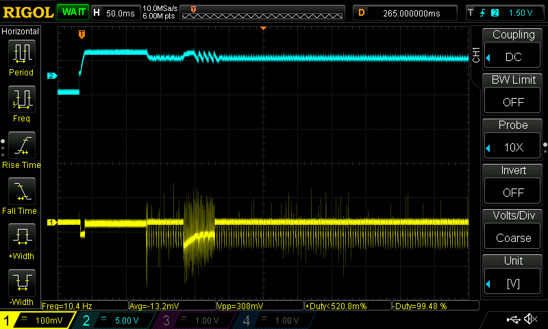
    Here is Vout during "bad" startup:

    Here is current during "bad" startup:

    Here is voltage on SWITCH_NODE suring "bad" startup:

    Tell me if you want me to measure the current at the inductor,  It's pretty involving to add a shunt there, I will se what I can do.

    Thank you for your help!

  • Note that I am switching on DCDC converter (blue trace is enable pin, please ignore noise on it, it's scoping issue) and then I am switching on the motor after 100ms.
  • Hi Albertas,

    The reason I ask you where the VCC voltage rail come from is the TPS61089 VCC pin cannot source too much current for external load. If this VCC comes from another rail, it will be OK.
    The motor load is a reactive load which is different from a resistor in Wenbench simulation. So the lope compensation may need to be designed carefully. From the wavefroms you show, when device is enabled, output voltage is normal to be 6V. However, with motor load, the SW pin will not swich for a lot of switch cycles and then will switch again. That's the reason output voltage will drop.
    It will he helpful for me to analysis if you can provide the SW pin wavefrom, inductor current and load current. Please zoom in the wavefroms as i can see them clearly.
  • Hi Zack,

    Today I am not in my lab so I can't provide the requested waveforms. I will do that on Monday. Can you advice how should I measure the inductor current waveform? Should I add a shunt resistor between the inductor and switch node?

    Yes I have noticed that regulator has no problem regulating before load is applied and goes into hickup mode when loaded. Note, this only happens when Vin is low. Motor is being PWMed, that also might be at play.

  • Hi Albertas,

    It will be nice if you have a current probe. Solder a wire in series with inductor and use the current probe to monitor the inductor current. If you don't have one, use a shunt resistor and differential probe to monitor the voltage across the shunt rersistor.
  • Hi Zack,

    I have traced the problem further today. It turned out to be caused by Vin dropping to 2.4V at the load turn on and UVLO of the chip kicking in. Now I ramp the load slowly and the system works fine.

    Regardless, advice regarding the compensation components for inductive load is still highly appreciated.