This thread has been locked.

If you have a related question, please click the "Ask a related question" button in the top right corner. The newly created question will be automatically linked to this question.

LM2733: LM2733Y usage as a 30 V/ 500 mA source

Part Number: LM2733

Greetings!
I have searched through the forums. Tried to use the Workbench, but it seems that a problem I have encountered is of another nature.

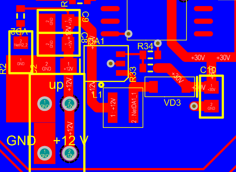
I have designed a PCB where I use LM2733 as a source for a ~500 mA load.
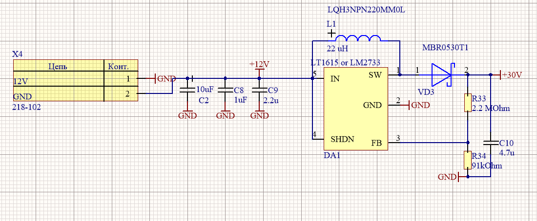
I use this one instead of the LT1615 device. So it is featable to the same pattern. I use a 2.2u as a IN cap. 4.7u as a OUT cap. 82p in parallel with R1. Feedback is 2.2meg R1 and 91k for R2. The diode is MBR0530. The inductor is LQH3NPN220MM0. 
When there is no load and when I start with 12V at the input I get 12V at the output. When I lower the VIN to 1.8V - the VOUT uppers to 30V.
When I put a 590 Ohm resistor in series with the VOUT I get around 22-24 volts at the output and 0.9 volts at the feedback.
Could you please provide me with help! I am truly ashamed also because I thought of ISW as of the output current available.

Thanks in advance

Alexander

  • Hi Alexander,

    Could you share the input voltage range, output voltage and output current requirement?

    It looks like you realize the difference between the switching current and output current. The LM2733 has 1A switching current, so it can't support 0.5 output current if VOUT is much larger than VIN. (the LT1615 has lower switching current)

    I would suggest you select a >1A and 10uH inductor. Could you also share the schematic and the layout?
  • Hello Jasper!

    Thanks for the reply! The input voltage is fixed  +12V. As I have metioned I need the LM2733 to give me +30V to feed a resistive load ~60Ohm.
    Also I mentioned which results I got during the experiment - please check them because there I have got really bizarre results.
    As for the currents - do I understand it correct in the way that Vin*Isw = TotalPowerAvailable and Iout=TotalPowerAvailable/Vout? So LT1615 can be used in much less power consuming curcuits?


  • Hi Alexander,

    We also need to consider the current ripple and efficiency when calculate the output current capability. please refer to the datasheet page 15 for the formula and figure. At VIN=12V, VOUT=30V, the output current would be approximately 300mA

    to find the root cause for the results you observed, we need to test the circuit step by step. (change the inductor to >1A saturation current inductor before experiment)
    1. in no load condition, measure the VIN, SW, VOUT waveform.
    2. slowly increase the load while watching the VIN, SW and VOUT waveform, capture the waveform if the VOUT is out of regulation.
  • Greetings Jasper!

    I have used the IHLP-2525CZER150M8A. That's the only inductor I have had that have rated current above 1 amp.

    So now it is like this:

    1. At the beginning the VOUT is eq to VIN; 
    2. When I lower the VIN to some value near 2-3 Volts - VOUT goes to +30V;
    3. The I make VIN to be +12V and I have +30V at the OUT.

    The load is 590 Ohm.

    Here are the waveforms: VIN, VOUT and VSW as is:

    Pity, but I am not able to make the higher load now - I do not have the power resistors needed for the purpose. The 590 Ohm resistor is 1210 and it heats a lot already.
    I will provide you with the waveforms with no loads in the next post.

  • Hi Alexander

    the inductor is OK. could you measure the FB pin voltage at VIN=12 condition? the waveform shows that the VOUT is also 12V at this condition
  • Hi Alexander

    I closed the post as not further feedback. it opens if you reply.